Supercharge Your Innovation With Domain-Expert AI Agents!

Liquid dispenser

Inactive Publication Date: 2009-02-26
MERCURIES ASIA
View PDF5 Cites 1 Cited by
  • Summary
  • Abstract
  • Description
  • Claims
  • Application Information

AI Technical Summary

Benefits of technology

[0007]The main objective of the present invention is to provide a liquid dispenser for a container to dispense liquid from the container precisely and easily.

Problems solved by technology

However, when a person stop pressing the push button, residual air pressure in the container forces additional liquid to be discharged from the spout that wastes liquid and causes the area around the container to be messy.
Furthermore, the liquid dispenser has a specific size and can be mounted only on a corresponding container and cannot be mounted on a container with a larger or smaller mouth.

Method used


Image

  • Liquid dispenser
  • Liquid dispenser
  • Liquid dispenser

Examples


Embodiment Construction

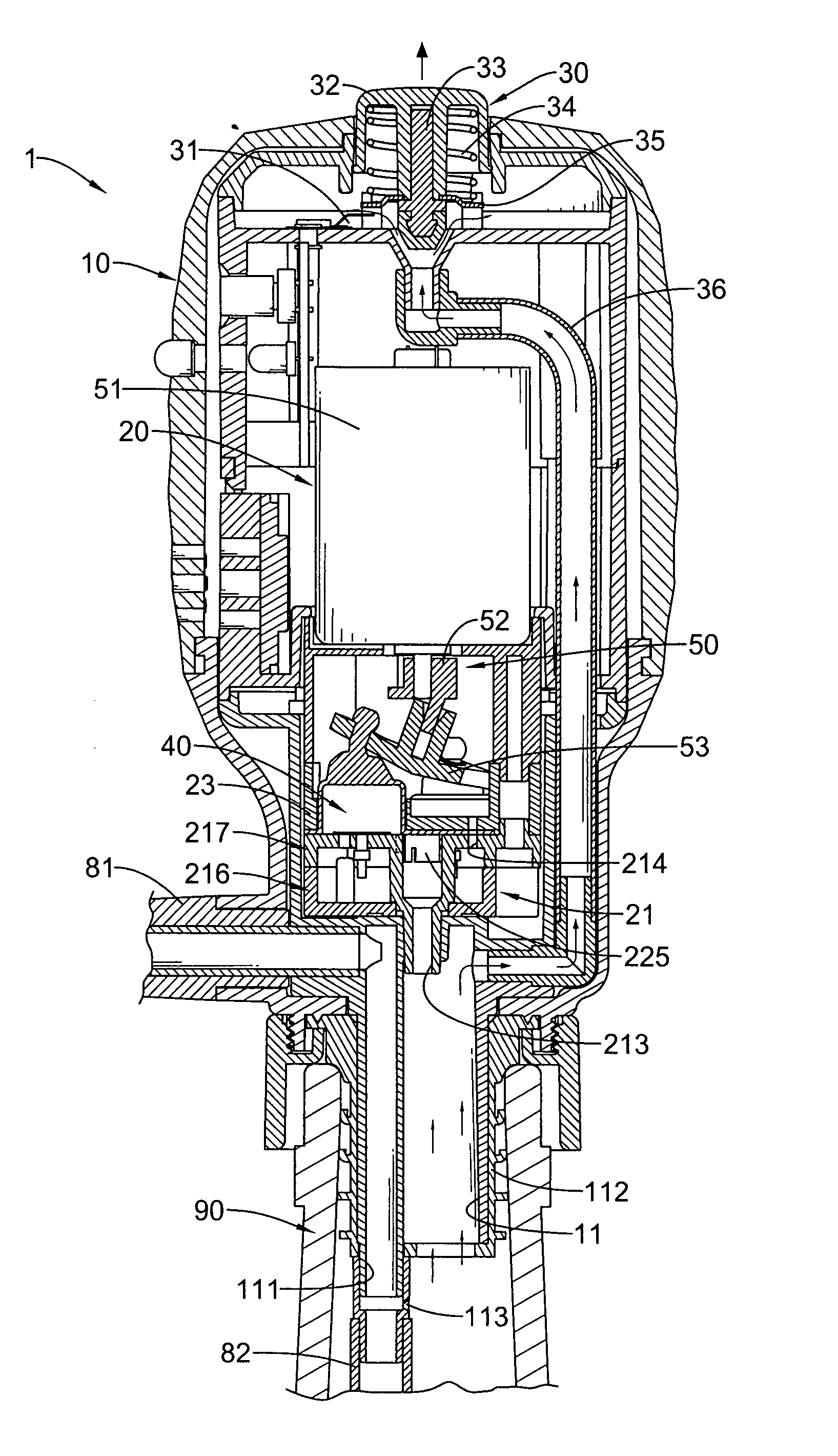
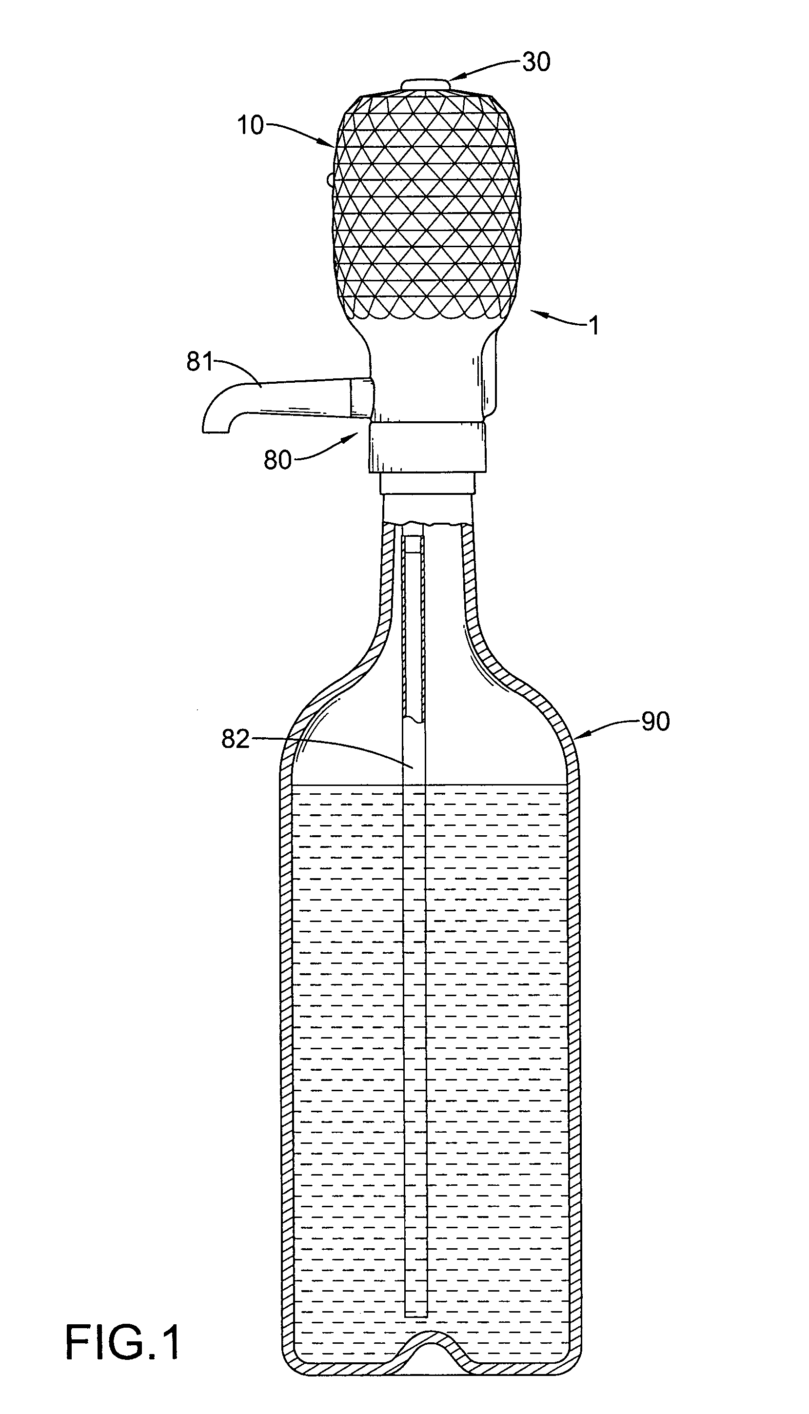
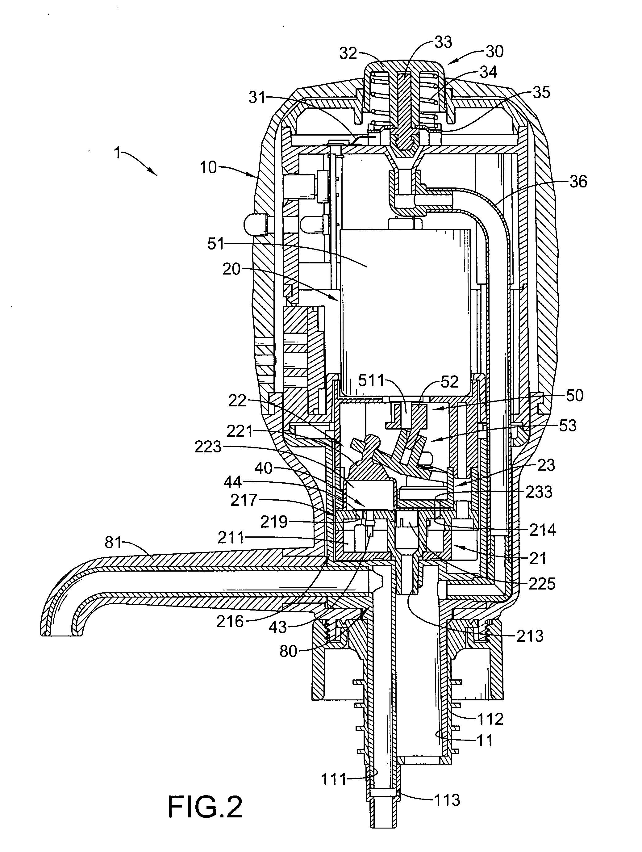
[0018]With reference to FIGS. 1, 2 and 5, a liquid dispenser (1) in accordance with the present invention is mounted on a container (90) having a top, a bottom and a mouth and comprises a shell (10), a spout assembly (80), an injection assembly (20), a power pack (60) and an activating assembly (30).

[0019]The shell (10) is hollow, is mounted on the mouth at the top of the container (90) and has a bottom, a top end, an injection tube (11) and multiple air ports. The injection tube (11) is formed on and protrudes longitudinally from the bottom of the shell (10) and has an internal surface, an external surface, an upper end, a discharge tube (111), an optional gasket (112) and an optional gas hole (113).

[0020]The discharge tube (111) is formed longitudinally on the internal surface of the injection tube (11) and has a top end and a bottom end.

[0021]The gasket (112) is mounted around the external surface of the injection tube (11) and presses against and seals the mouth of the container...


PUM


Abstract

A liquid dispenser is mounted on a container and has a shell, a spout assembly, an injection assembly, a power pack and an activating assembly. The shell is mounted on the container and has an injection tube. The spout assembly is formed on and protrudes from the shell. The injection assembly is mounted in the shell pumps air into the injection tube to force liquid from the spout assembly. The activating assembly selectively activates the injection assembly and selectively seals or opens an air passage to the injection tube.

Description

BACKGROUND OF THE INVENTION[0001]1. Field of the Invention[0002]The present invention relates to a liquid dispenser, and more particularly to a liquid dispenser mounted on a container and dispensing liquid from the container precisely and easily.[0003]2. Description of Related Art[0004]Conventional liquid dispensers may be manual or automatic, are mounted on a container holding a liquid and having a top and a bottom and usually comprise a top, a spout, a push button, an air pump, an discharge tube and a pick-up tube. The push button is mounted on the top of the liquid dispenser. The spout protrudes transversely from the liquid dispenser and has an inner end. The air pump is mounted in the liquid dispenser below the push button and is operated and expels air into the container by pressing the push button. The discharge tube is connected to and communicates with the bottom of the air pump. The pick-up tube is connected to the liquid dispenser and extends to the bottom of the container...

Claims


Application Information

Patent Timeline
IPC IPC(8): B65D37/00B65D88/54
CPCB05B9/0805F04B45/047F04B45/043B05B9/0811B67D1/0006B67D1/0431
Inventor HUANG, YI-CHUNGHUANG, YU-JUNG
Owner MERCURIES ASIA
Features
  • R&D
  • Intellectual Property
  • Life Sciences
  • Materials
  • Tech Scout
  • Unparalleled Data Quality
  • Higher Quality Content
  • 60% Fewer Hallucinations
Learn More