Slide locking device

a locking device and sliding technology, applied in the direction of wing openers, door/window fittings, constructions, etc., can solve the problems of lack of smoothness in locking and unlocking, lack of simple and compact structure for locking and unlocking, etc., to achieve smooth locking of the locking part, and smooth locking of the movement

a locking device and sliding technology, applied in the direction of wing openers, door/window fittings, constructions, etc., can solve the problems of lack of smoothness in locking and unlocking, lack of simple and compact structure for locking and unlocking, etc., to achieve smooth locking of the locking part, and smooth locking of the movement

US20090051171A1Inactive Publication Date: 2009-02-26NHK SPRING CO LTD

Image

  • Slide locking device
  • Slide locking device
  • Slide locking device

Examples


Embodiment Construction

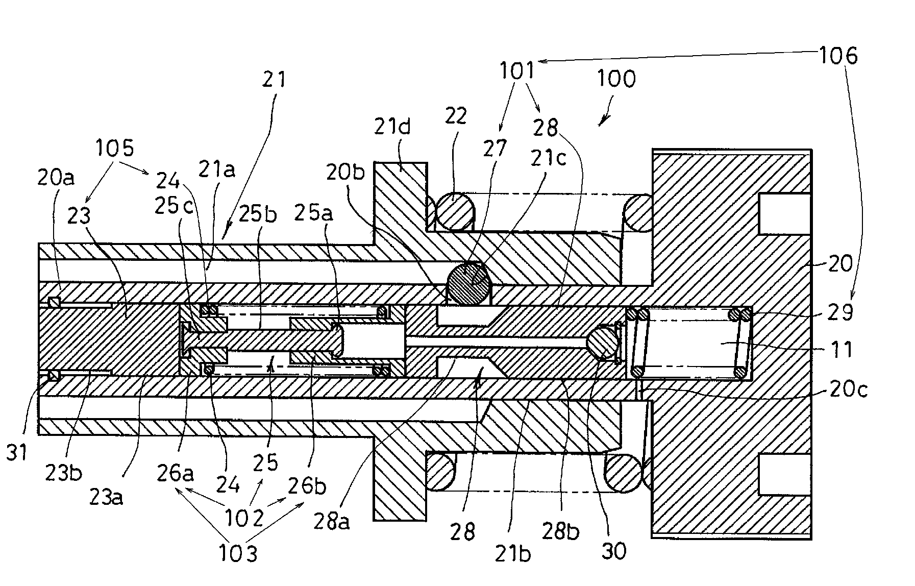
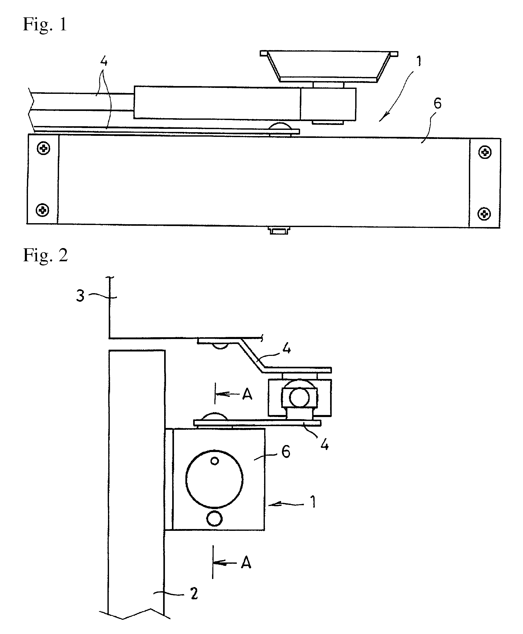
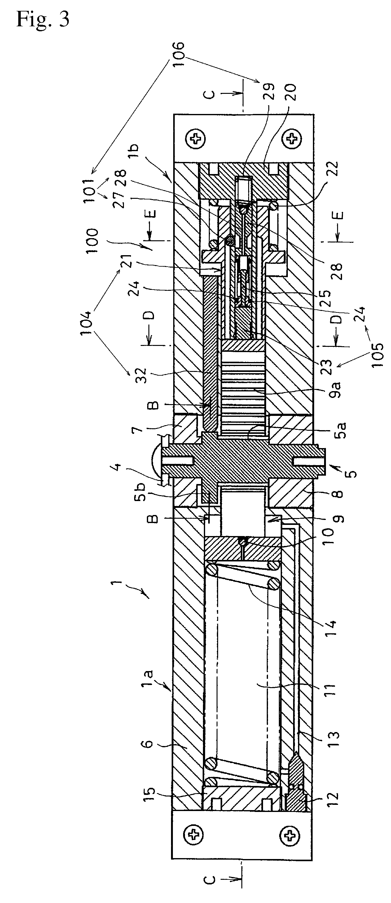
[0071]The slide locking device of the present invention will now be described in detail with reference to an embodiment in which the slide locking device is incorporated in a door-opening-assistance device. In this embodiment, the door-opening-assistance device is structured so as to be integrated with a door closer. Accordingly, the slide locking device is also incorporated in the door closer. FIGS. 1 to 29 show one embodiment of the door closer. FIG. 1 is a front view, FIG. 2 is a left side view of the door closer shown in FIG. 1, FIG. 3 is a cross-section view along the line A-A of FIG. 2, FIG. 4 is a cross-section view along a line B-B of FIG. 3, FIG. 5 is a cross-section view along a line C-C of FIG. 3, FIG. 6 is a cross-section view along a line D-D of FIG. 3, FIG. 7 is a cross-section view along a line E-E of FIG. 3, FIG. 8 is a cross-section view of the interior of the slide locking device, FIGS. 9 to 23 show the actions of the door closer, and FIGS. 24 to 29 show the action...


PUM


Abstract

This slide locking device is incorporated in a opening-assistance device, so as to smoothly lock and unlock a reciprocating part so that it can move in opposite directions. The device includes a reciprocating part 21 that can move forward and backward in the device's longitudinal direction, locking parts 101 that can be engaged with or disengaged from the reciprocating part 21, and that lock the movement of the reciprocating part 21 when engaged with the reciprocating part 21, a first elastic part 24 that applies force to the locking parts 101 so as to move the locking parts 101 in the direction that disengages them from the reciprocating part 21, a second elastic part 29 that applies force to the locking parts 101 so as to move the locking parts 101 in the direction that engages them with the reciprocating part 21, and holding means 102 that hold the first elastic part 24 in a condition for storing an elastic force that is larger than the maximum elastic force of the second elastic part 29, and that prevent the elastic force of the first elastic part 24 from acting against the second elastic part 29 when the second elastic part 29 moves the locking parts 101 in the direction that engages them with the reciprocating part 21.

Description

CROSS-REFERENCE TO RELATED APPLICATIONS[0001]The present Application is based on International Application No. PCT / JP2006 / 301491 filed on Jan. 30, 2006, which in turn corresponds to Japan Application No. 2005-027098 filed on Feb. 2, 2005 and priority is hereby claimed under 35 USC § 119 based on these applications. Each of these applications are hereby incorporated by reference in their entirety into the present application.FIELD OF THE INVENTION[0002]The present invention relates to a slide locking device for locking and unlocking the movement—in the longitudinal direction—of a reciprocating part on, for instance, a door-opening-assistance device.BACKGROUND OF THE INVENTION[0003]A slide locking device is incorporated, for example, in a door-opening-assistance device that assists a person by giving additional force in the door-opening direction in opening a door. The door-opening-assistance device is mounted to a door closer that automatically closes the door, so as to reduce the am...

Claims


Application Information

Patent Timeline
26 Feb 2009
Publication
US20090051171A1
IPC
E05F1/10
CPC
E05F1/1041; E05F1/14; E05F3/227; E05Y2900/132; E05F3/102; Y10T292/0969
Inventors
YAMAMURO, KOICHI