Supercharge Your Innovation With Domain-Expert AI Agents!

PON system and terminal operation registering method

a terminal and operation registration technology, applied in the field of pon system and terminal operation registration method, can solve the problems of inability of the terminal to perform upstream communication, inability to establish synchronization, and inability to transmit registration request signals at the transmission ra

Active Publication Date: 2009-02-26
SUMITOMO ELECTRIC IND LTD
View PDF2 Cites 37 Cited by
  • Summary
  • Abstract
  • Description
  • Claims
  • Application Information

AI Technical Summary

Benefits of technology

The present invention provides a method for quickly and reliably registering a terminal in a PON system. The method involves setting a discovery period for allowing the station apparatus to recognize an unregistered terminal and notifying the terminal of the discovery period. The terminal, in response, makes a discovery response at a specified predetermined transmission rate among the plurality of types of transmission rate. By doing so, the station apparatus can wait for a discovery response with the receive function being narrowed down to the predetermined transmission rate, resulting in a faster and more reliable reception of a discovery response from an unregistered terminal. The predetermined transmission rate can be specified by the station apparatus or changed based on the times. The invention also provides a terminal registering method for the PON system.

Problems solved by technology

However, even if provision of high transmission rate services begins, not all subscribers want the services at the same time, resulting in a multi-rate PON system in which for upstream communication, an existing transmission rate and a high transmission rate exceeding the existing transmission rate coexist in one PON system (see, for example, Japanese Patent Laying-Open No. 8-8954 (FIG. 2)).
However, for example, a terminal that attempts to participate in the PON system by power-on from a power-off state is not yet recognized by the station apparatus at that point and thus the terminal does not have a chance to perform upstream communication.
However, even in such a case, since the terminal that attempts to participate is not yet under the control of the station apparatus, it is completely unknown at which transmission rate a registration request signal is to be transmitted.
Accordingly, it is not always that the station apparatus always succeeds in receiving a registration request signal, and even if succeeded, it takes time to establish synchronization.
Namely, the terminal that attempts to participate in the PON system cannot be promptly and reliably registered.

Method used


Image

  • PON system and terminal operation registering method
  • PON system and terminal operation registering method
  • PON system and terminal operation registering method

Examples


Embodiment Construction

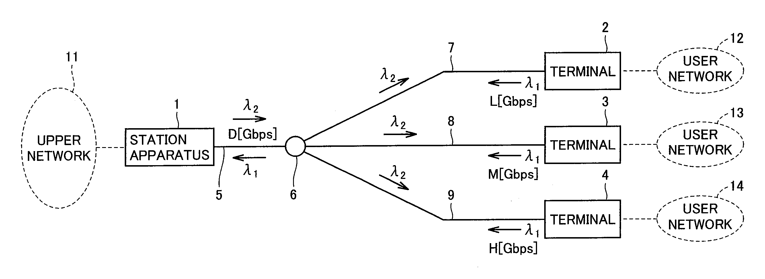
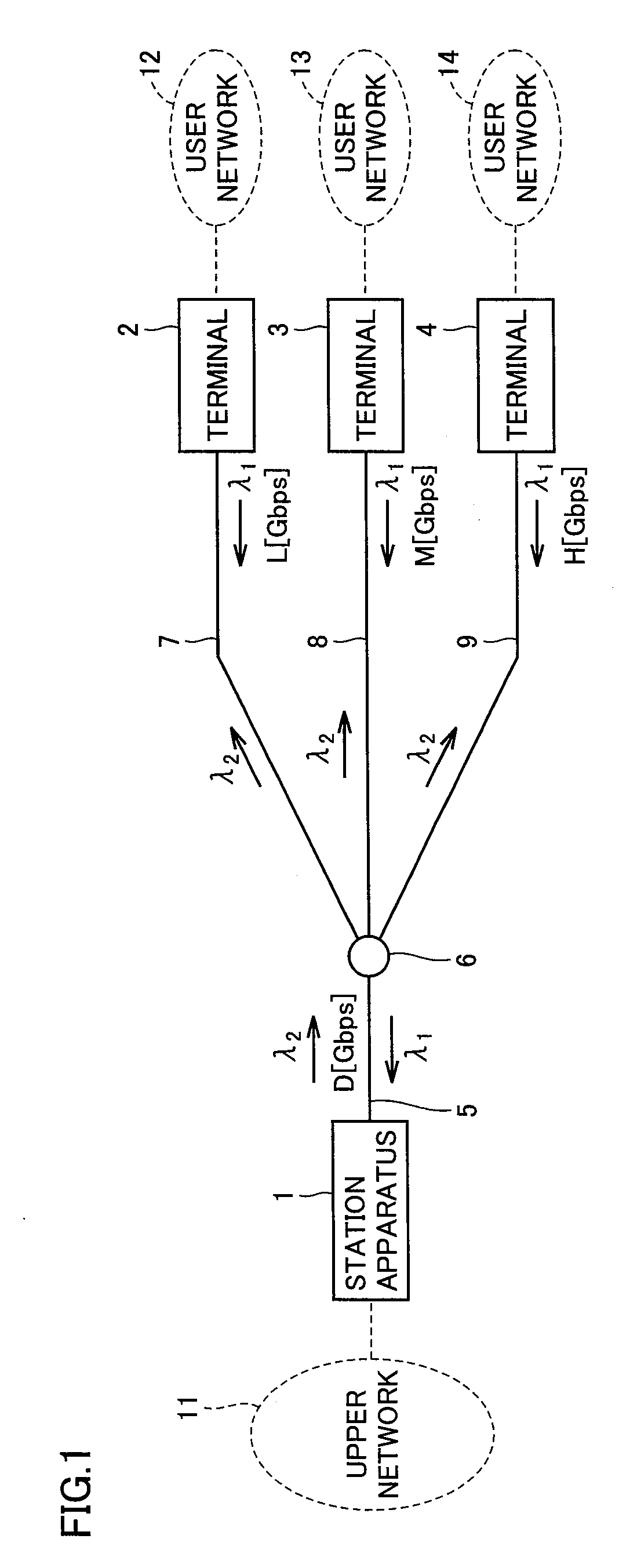
[0027]FIG. 1 is a connection diagram of a PON system according to one embodiment of the present invention. In the drawing, a station apparatus 1 is installed as an aggregate station for a plurality of terminals 2 to 4. Terminals 2 to 4 are respectively installed in PON system subscribers' homes. An optical fiber network (5 to 9) is configured in which one optical fiber 5 connected to station apparatus 1 is branched into a plurality of optical fibers (branch lines) 7 to 9 through an optical coupler 6, and terminals 2 to 4 are connected to the respective terminal ends of branched optical fibers 7 to 9. Furthermore, station apparatus 1 is connected to an upper network 11 and terminals 2 to 4 are connected to their corresponding user networks 12 to 14.

[0028]Note that although FIG. 1 shows three terminals 2 to 4, it is possible to branch into, for example, 32 through one optical coupler 6 to connect 32 terminals. Note also that although in FIG. 1 only one optical coupler 6 is used, by pr...


PUM


Abstract

In a PON system in which communication is performed at a plurality of types of transmission rate (L, M, and H) in an upstream direction from a plurality of terminals connected to a station apparatus through optical fibers, within a discovery period for allowing an unregistered terminal to be recognized by station apparatus, the terminal makes a discovery response at one type of transmission rate (L). With this configuration, station apparatus can wait for a discovery response with a receive function being allowed to support transmission rate (L).

Description

TECHNICAL FIELD[0001]The present invention relates to a PON (Passive Optical Network) system that connects a station apparatus to a plurality of terminals by an optical fiber network.BACKGROUND ART[0002]A PON system is one in which a station apparatus serving as an aggregate station is connected to terminals installed in a plurality of subscribers' homes by an optical fiber network that branches one optical fiber into a plurality of optical fibers through an optical coupler (see, for example, Japanese Patent Laying-Open No. 2004-64749 (FIG. 4) and Japanese Patent Laying-Open No. 2004-289780 (FIG. 31)). Upstream burst communication from the terminals to the station apparatus is managed in a time-sharing manner by the station apparatus in order to prevent signal collisions.[0003]Although initially such upstream burst communication is considered at a certain transmission rate, in the future a stepwise increase in transmission rate is expected. However, even if provision of high transmi...

Claims


Application Information

Patent Timeline
Patent Type & Authority Applications(United States)
IPC IPC(8): H04J14/00H04L12/44
CPCH04J3/1694H04B10/27H04J14/02H04L12/44H04J3/16
Inventor MURATA, HIROSHI
Owner SUMITOMO ELECTRIC IND LTD
Features
  • R&D
  • Intellectual Property
  • Life Sciences
  • Materials
  • Tech Scout
  • Unparalleled Data Quality
  • Higher Quality Content
  • 60% Fewer Hallucinations
Learn More