Systems and methods for providing deeper knee flexion capabilities for knee prosthesis patients

a knee prosthesis and patient technology, applied in the field of knee prosthesis, can solve the problems of inability of knee prosthesis patients to achieve, many shortcomings of the prosthesis, and uncommon prosthesis results, and achieve the effect of deep knee flexion capabilities, full functional flexion, and greater articular surface area

Inactive Publication Date: 2009-03-05
SAMUELSON KENT M
View PDF29 Cites 40 Cited by
  • Summary
  • Abstract
  • Description
  • Claims
  • Application Information

AI Technical Summary

Benefits of technology

[0014]The present invention relates to knee prostheses. In particular, the present invention relates to systems and methods for providing deeper knee flexion capabilities for knee prosthesis patients, and more particularly, to: (i) providing a greater articular surface area to the femoral component of a knee prosthesis, with either a modification of, or an attachment to the femoral component of a knee prosthesis, which when integrated with a patient's femur and an appropriate tibial component, results in full functional flexion; (ii) providing modifications to the internal geometry of the femoral component and the opposing femoral bone with methods of implanting; (iii) providing asymmetrical under surfaces on the tibial component of the knee prosthesis and uniquely-positioned articular surfaces to facilitate full functional flexion; and (iv) asymmetrical femoral condylar surfaces with a lateralized patellar (trochlear) groove to more closely replicate physiologic loading of the knee and to provide better tracking of the patella.
[0015]Implementation of the present invention takes place in association with improved knee prostheses that enable knee prosthesis patients to achieve greater deep knee flexion than previously achievable using presently-designed knee prostheses.
[0016]In at least some implementations of the present invention, greater deep knee flexion is provided to the knee prosthesis by providing an articular surface on the proximal, anterior surface (or portion) of the posterior condyles of the femur. At least some implementations of the present invention embrace an additional or increased articular surface on the proximal, anterior portion of either or both of the medial or lateral posterior condyles of the femoral component of the prosthesis. Embodiments of the femoral component add increased articular surface area to the proximal end of the posterior condyles of the femoral component in an anterior direction such that when the patient bends his or her knee during deep knee flexion, contact between the femoral component and the tibial component is maintained, and a greater, deeper knee flexion can be achieved.
[0017]In at least some implementations of the present invention, greater deep knee flexion can be provided or improved by modifying the tibial articulation, in which the center of the conforming medial tibial articular surface of the tibial component of the prosthesis is moved posterior relative to what is currently available. Additionally, in some such embodiments, the overall shape of the lateral tibial articular surface is modified.

Problems solved by technology

Unfortunately, today's knee prostheses still have many shortcomings.
Though some currently available knee prostheses allow for knee flexion (i.e., bending) of more than 130 degrees from full limb extension (zero degrees being when the patient's knee is fully extended and straight); such prostheses and results are uncommon.
Most knee prosthesis patients are unable to achieve the latter position or any position placing the knee joint at angles above 130 degrees.
For many people, such a limb and body position is not often achieved or desired most of the time.
Unfortunately, those with currently-available knee prostheses are unable to participate in any activity requiring greater knee flexion and are thus limited to watching from the sidelines.
For instance, in Asian and Indian cultures, full functional flexion and the squatting position is common and performed for relatively long periods of time.
Thus, while techniques currently exist that relate to knee prostheses, challenges still exist.

Method used


Image

  • Systems and methods for providing deeper knee flexion capabilities for knee prosthesis patients
  • Systems and methods for providing deeper knee flexion capabilities for knee prosthesis patients
  • Systems and methods for providing deeper knee flexion capabilities for knee prosthesis patients

Examples


Embodiment Construction

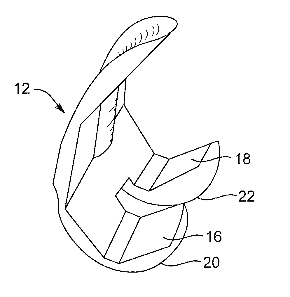
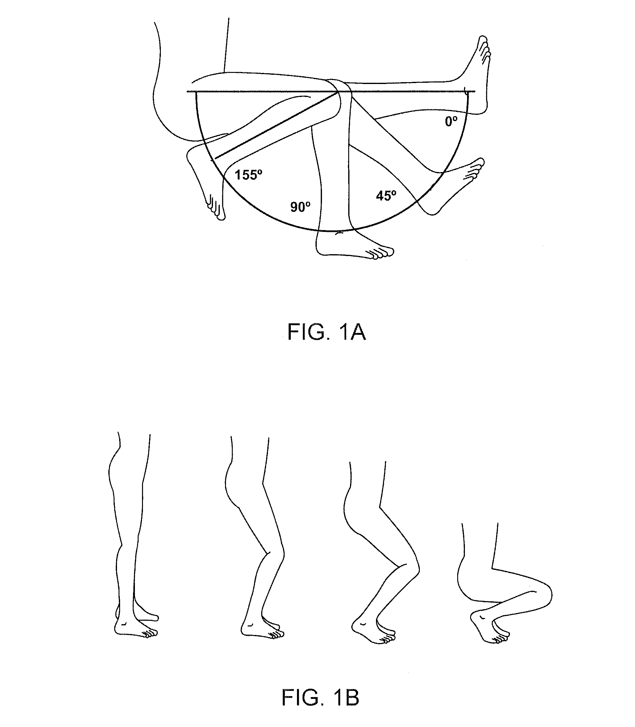
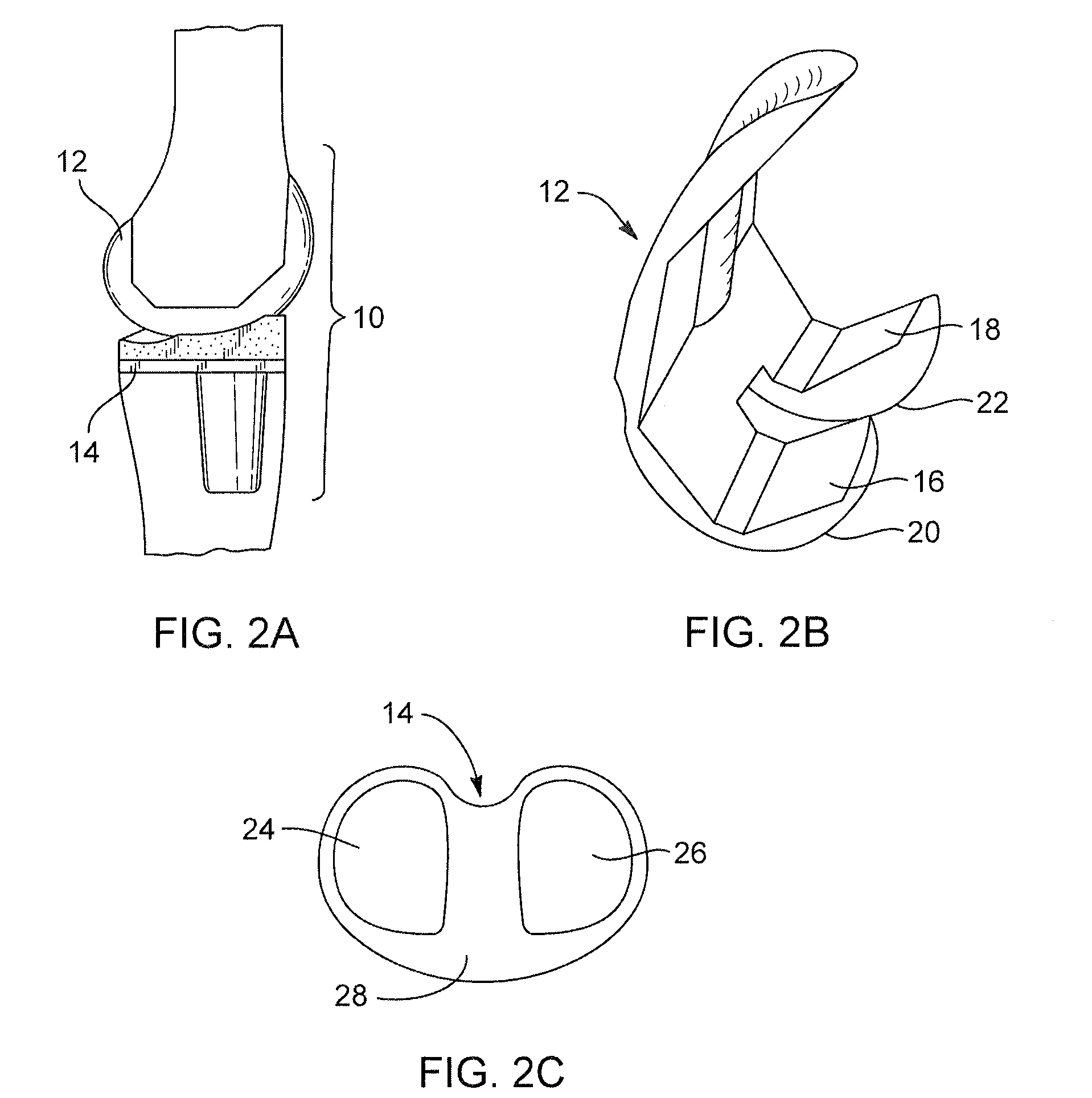
[0047]The present invention relates to knee prostheses. In particular, the present invention relates to systems and methods for providing deeper knee flexion capabilities for knee prosthesis patients, and more particularly, to: (i) providing an extended articular surface on the proximal, anterior surface (or portion) of the posterior condyles of the femur; (ii) making modifications to the internal geometry of the femoral component and the associated femoral bone cuts with methods of implantation; (iii) making modifications to the tibial and femoral components of a knee prosthesis, including asymmetrical tibial articular surfaces and removing certain areas of the tibial and femoral components; and (iv) having asymmetric femoral condyles, including having a closing radius on the femoral component, wherein all of the foregoing result in deeper knee flexion capabilities for knee prosthesis patients than previously achievable.

[0048]It is emphasized that the present invention, as illustra...


PUM


Abstract

Systems and methods for providing deeper knee flexion capabilities, more physiologic load bearing and improved patellar tracking for knee prosthesis patients. Such systems and methods include (i) adding more articular surface to the antero-proximal posterior condyles of a femoral component, including methods to achieve that result, (ii) modifications to the internal geometry of the femoral component and the associated femoral bone cuts with methods of implantation, (iii) asymmetrical tibial components that have an unique articular surface that allows for deeper knee flexion than has previously been available and (iv) asymmetrical femoral condyles that result in more physiologic loading of the joint and improved patellar tracking.

Description

CROSS-REFERENCE TO RELATED APPLICATIONS[0001]This application claims priority to U.S. Provisional Patent Application Ser. No. 60 / 968,246, filed Aug. 27, 2007, and entitled SYSTEMS AND METHODS FOR PROVIDING DEEPER KNEE FLEXION CAPABILITIES FOR KNEE PROSTHESIS PATIENTS, and to U.S. Provisional Patent Application Ser. No. 60 / 972,191, filed Sep. 13, 2007, and entitled SYSTEMS AND METHODS FOR PROVIDING DEEPER KNEE FLEXION CAPABILITIES FOR KNEE PROSTHESIS PATIENTS, each of which is incorporated herein in its entirety by reference.BACKGROUND OF THE INVENTION[0002]1. Field of the Invention[0003]The present invention relates to knee prostheses. In particular, the present invention relates to systems and methods for providing deeper knee flexion, or full functional flexion capabilities, more physiologic load bearing and improved patellar tracking for knee prosthesis patients. Specifically, these improvements include (i) adding more articular surface to the antero-proximal posterior condyles o...

Claims


Application Information

Patent Timeline
Patent Type & Authority Applications(United States)
IPC IPC(8): A61F2/36
CPCA61B17/155A61F2/3859A61F2/30734
Inventor SAMUELSON, KENT M.
Owner SAMUELSON KENT M
Why Eureka
Try Eureka