
Power sharing between midspan and endspan for higher power PoE

a technology of power sharing and power sharing, applied in the field of power over ethernet, can solve the problems of system limitations to support higher power supply in poe systems, system upgrade to increase power supply might be very difficult or require complete replacement of system equipmen

Active Publication Date: 2009-03-05
AVAGO TECH INT SALES PTE LTD
View PDF3 Cites 34 Cited by
  • Summary
  • Abstract
  • Description
  • Claims
  • Application Information

AI Technical Summary

Benefits of technology

The patent text describes methods and systems for improving the power capacity of a PoE system. The invention uses an endspan-midspan configuration to allocate power to the PD from both an endspan PSE and a midspan PSE, allowing for more efficient use of the Ethernet cable's maximum power transmission capacity. The invention also includes power management schemes to intelligently allocate power between the two PSEs based on the required power for the PD. Overall, the invention improves the overall power capacity and efficiency of the PoE system.

Problems solved by technology

Today, enabling higher power PoE systems that comply with current IEEE PoE standards faces challenges.
Particularly, system limitations exist to supporting higher power supply in PoE systems.
These limitations are most problematic in the case of already deployed PoE systems, where a system upgrade to increase power supply might be very difficult or require complete replacement of system equipment.

Method used


Image

  • Power sharing between midspan and endspan for higher power PoE
  • Power sharing between midspan and endspan for higher power PoE
  • Power sharing between midspan and endspan for higher power PoE

Examples


Embodiment Construction

)

Overview

[0027]Today, enabling higher power PoE systems that comply with current IEEE PoE standards faces challenges. Particularly, system limitations exist to supporting higher power supply in PoE systems. These limitations are most problematic in the case of already deployed PoE systems, where a system upgrade to increase power supply might be very difficult or require complete replacement of system equipment. Indeed, while it may be easy to upgrade a chassis-based system's line card to support higher power levels per port, it is very difficult to scale a system's power supply to provide higher power as most chassis systems are already deployed. This may be the case, for example, for existing PoE systems having limited power supply capabilities and / or ports designed for lower power (e.g., chassis or stackable PoE systems).

[0028]Accordingly, there is a need to overcome the above described system limitations to enable higher power PoE systems.

[0029]Embodiments of to the present inve...


PUM


Abstract

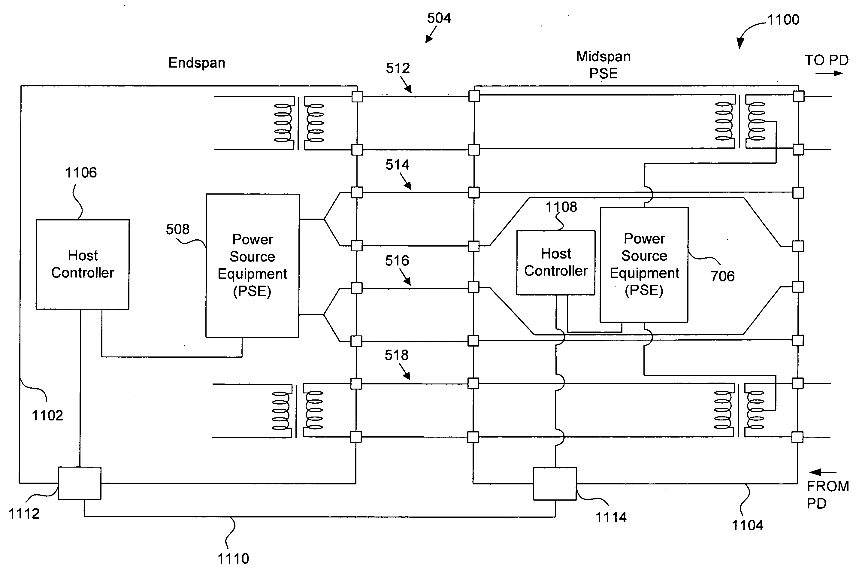
Methods and systems for higher power PoE are provided. Embodiments overcome system limitations to PSE power scaling by using an endspan-midspan configuration which allocates power to the PD from both an endspan PSE and a midspan PSE. Embodiments are particularly suitable for deployed PoE systems having limited power supplies and / or ports designed for lower power. Further, embodiments include power management schemes to enable the proposed endspan-midspan configuration to intelligently allocate power between the endspan PSE and the midspan PSE according to required PD power.

Description

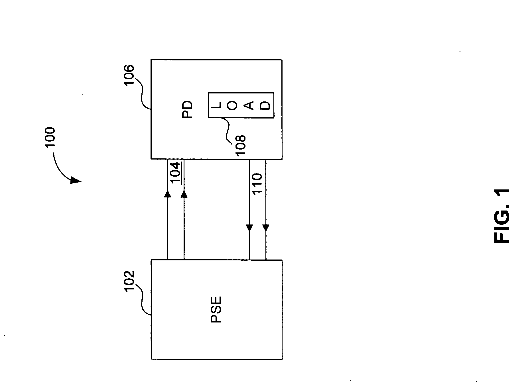
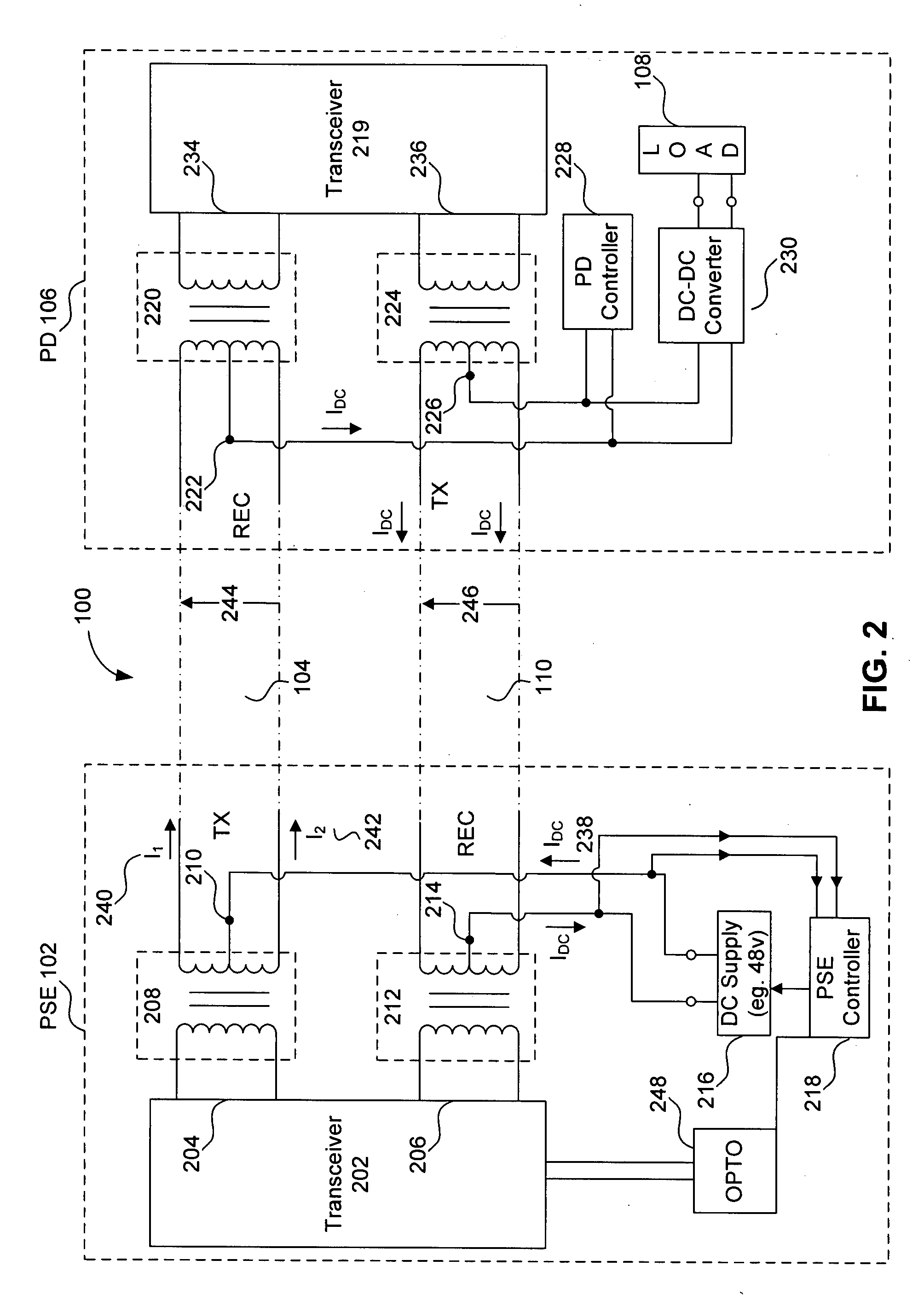
CROSS-REFERENCE TO RELATED APPLICATIONS[0001]The present application claims the benefit of U.S. Provisional Patent Application No. 60 / 935,703, filed Aug. 27, 2007 (Atty. Docket No. 2875.1680000), which is incorporated herein by reference in its entirety.BACKGROUND OF THE INVENTION[0002]1. Field of the Invention[0003]The present invention relates generally to Power over Ethernet (PoE), and more particularly to higher power PoE.[0004]2. Background Art[0005]Ethernet communications provide high speed communications between data terminals.[0006]Power over Ethernet (PoE) systems enable power transmission over the same transmission lines that carry data in an Ethernet link. Generally, power is generated at a Power Source Equipment (PSE) side of the PoE system and is carried over an Ethernet cable to a Powered Device (PD) side of the PoE system.[0007]Today, enabling higher power PoE systems that comply with current IEEE PoE standards faces challenges. Particularly, system limitations exist ...

Claims


Application Information

Patent Timeline
Patent Type & Authority Applications(United States)
IPC IPC(8): G06F1/26
CPCH04L12/10G06F1/266
Inventor DIAB, WAEL WILLIAM
Owner AVAGO TECH INT SALES PTE LTD
Learn More