Environmental sensing unit

a sensing unit and environmental technology, applied in the field of environmental sensing units, can solve the problems of wasting energy and money, affecting the accuracy of this type of sensor, and affecting the accuracy of the sensor at times of low occupancy,

Active Publication Date: 2009-03-12
VERIS INDS
View PDF18 Cites 22 Cited by
  • Summary
  • Abstract
  • Description
  • Claims
  • Application Information

AI Technical Summary

Problems solved by technology

However, heating, cooling, humidifying and moving this volume of air at times when the occupancy is low is wasteful of energy and expensive.
The accuracy of this type sensor is often insufficient for a ventilation system and the devices are subject to deterioration in harsh environments.
Chemical sensors comprise materials that are sensitiv...

Method used


Image

  • Environmental sensing unit
  • Environmental sensing unit
  • Environmental sensing unit

Examples


Embodiment Construction

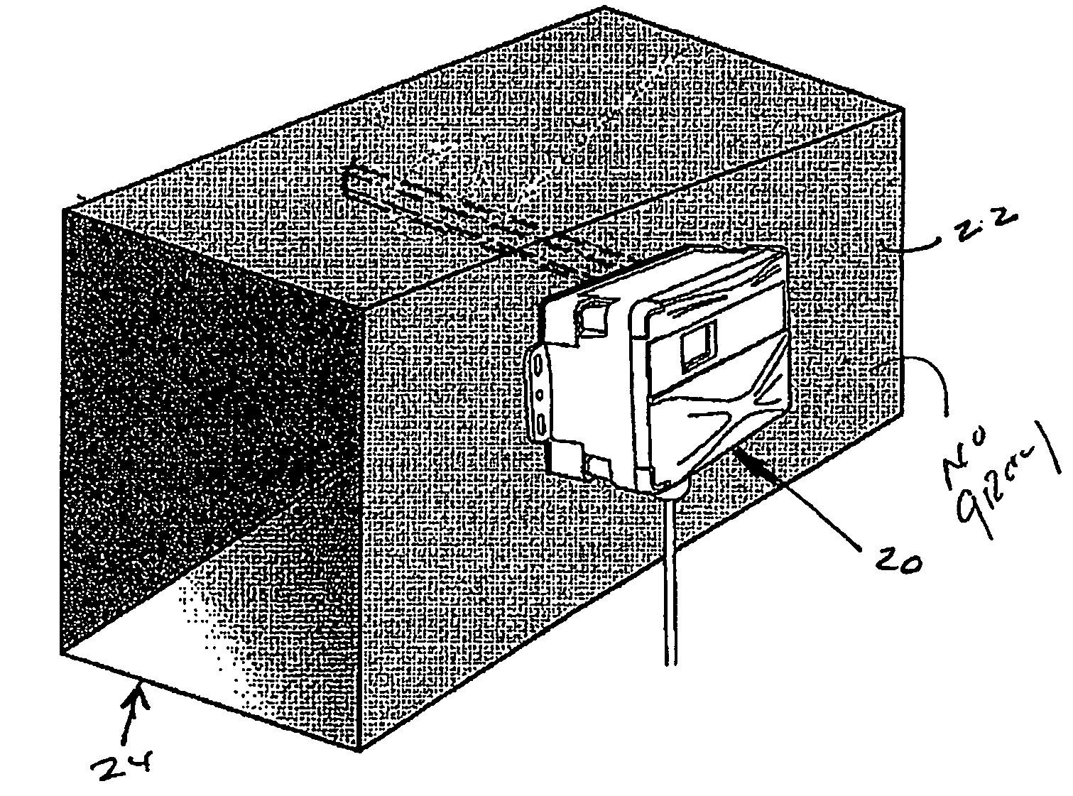
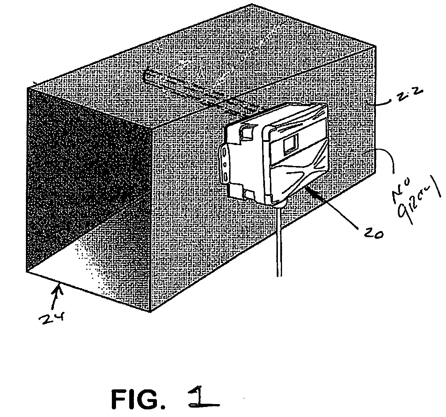
[0016]Building codes commonly specify ventilation requirements for indoor spaces on a per-person basis. In the past, sufficient ventilation was provided at all times to satisfy the per person requirements of a fully occupied space. However, building occupancy varies throughout a day and often varies from day-to-day and considerable energy is required to heat, cool, humidify and move the replacement air. Providing full occupancy ventilation, even on a periodically varying basis, can be very energy inefficient and expensive. Demand controlled ventilation seeks to optimize occupant comfort and well being and energy consumption under conditions of variable and intermittent occupancy by varying the amount of outside air added to the space in response to changes in the occupancy. The level of carbon dioxide (CO2) in the environment is an indicator of the presence of other pollutants that effect human performance and, since carbon dioxide is a product of human respiration, its concentratio...


PUM


Abstract

A duct mounted environmental sensing unit includes a plurality of sensors for detecting respective parameters of a fluid in a duct. The sensing unit enables at least three sensors to make contact with the fluid through a single insertion point in the duct.

Description

CROSS-REFERENCE TO RELATED APPLICATIONS[0001]This application claims the benefit of U.S. Provisional App. No. 60 / 993,220, filed Sep. 10, 2007.BACKGROUND OF THE INVENTION[0002]The present invention relates to environmental sensors for detecting characteristics of a fluid in a duct and, more particularly, to a duct mounted environmental sensing unit for detecting a plurality of parameters of a fluid in a duct of a heating, cooling and ventilation system.[0003]Temperature and humidity are primary factors in the comfort and quality of an indoor environment. While temperature is important to comfort, the humidity is a substantial factor in determining whether a specific temperature is comfortable. Temperature is commonly regulated as a function of the relative humidity in a space and humidifiers, to control the relative humidity, are often a part of the heating, cooling and ventilation systems of office buildings and industrial plants.[0004]Carbon dioxide (CO2) is a product of human resp...

Claims


Application Information

Patent Timeline
IPC IPC(8): G01N25/00G01N7/00G01N19/10
CPCG01K13/02G01N33/0032G01N27/048G01K2201/00Y02B30/70
Inventor PETTIT, CASEYVERNON, MATHEWSOENNICHSEN, RICH
Owner VERIS INDS
Why Eureka
Try Eureka