
Gas separator within esp shroud

a technology of gas separator and shroud, which is applied in the direction of liquid degasification, separation process, and borehole/well accessories, etc., can solve the problems of separator not being incorporated, head degradation, gas locking, etc., and achieves the effect of increasing the passive separation of fluids and enhancing the formation of vortex

Inactive Publication Date: 2009-03-12
BAKER HUGHES INC
View PDF4 Cites 60 Cited by
  • Summary
  • Abstract
  • Description
  • Claims
  • Application Information

AI Technical Summary

Benefits of technology

[0008]In this invention, a gas separator is mounted to the ESP. A shroud encloses at least a portion of the ESP and the gas separator. The gas separator has a passage that extends from its gas outlet through the shroud for discharging the lighter components exterior of the shroud. Preferably the passage is substantially tangent to an outer diameter portion of the shroud at the gas outlet. Making the passage tangent enhances the formation of a vortex as the gas discharges. The vortex increases the passive separation of the fluids by continuing to cause coalescing of bubbles in the fluid as it exits.

Problems solved by technology

Centrifugal pumps are mainly designed to handle liquid and will suffer from head degradation and gas locking in the presence of a high percentages of free gas.
Normally, a gas separator would not be incorporated with a shrouded ESP because of the problem of disposing of the gas into the well fluid flowing toward the inlet of the shroud.
If the shroud inlet is on the upper end, any gas discharged from the gas separator would flow upward through the annulus surrounding the shroud and might fail to separate from the liquid at the inlet of the shroud where the well fluid begins flowing downward.

Method used


Image

  • Gas separator within esp shroud
  • Gas separator within esp shroud
  • Gas separator within esp shroud

Examples


Embodiment Construction

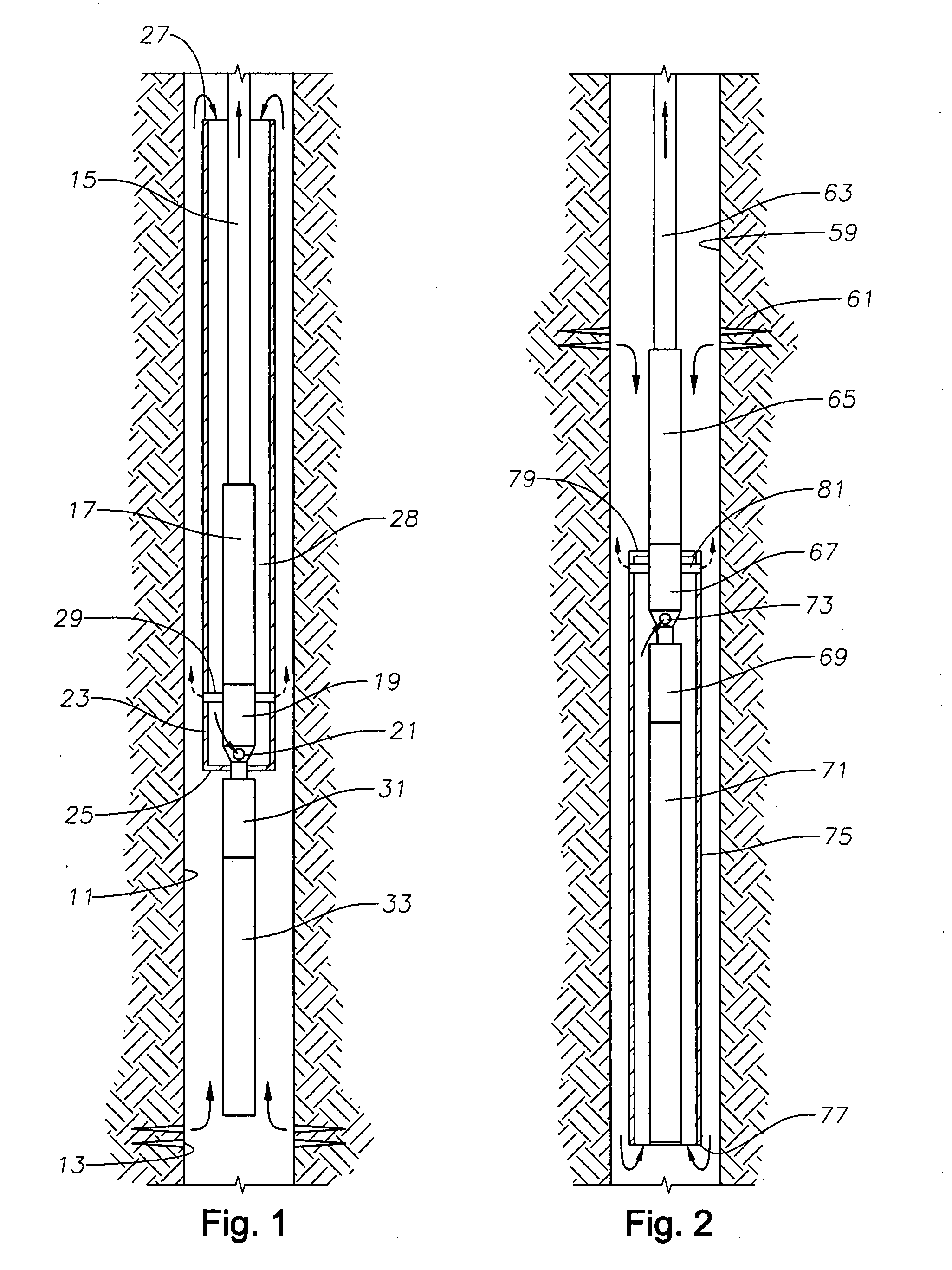
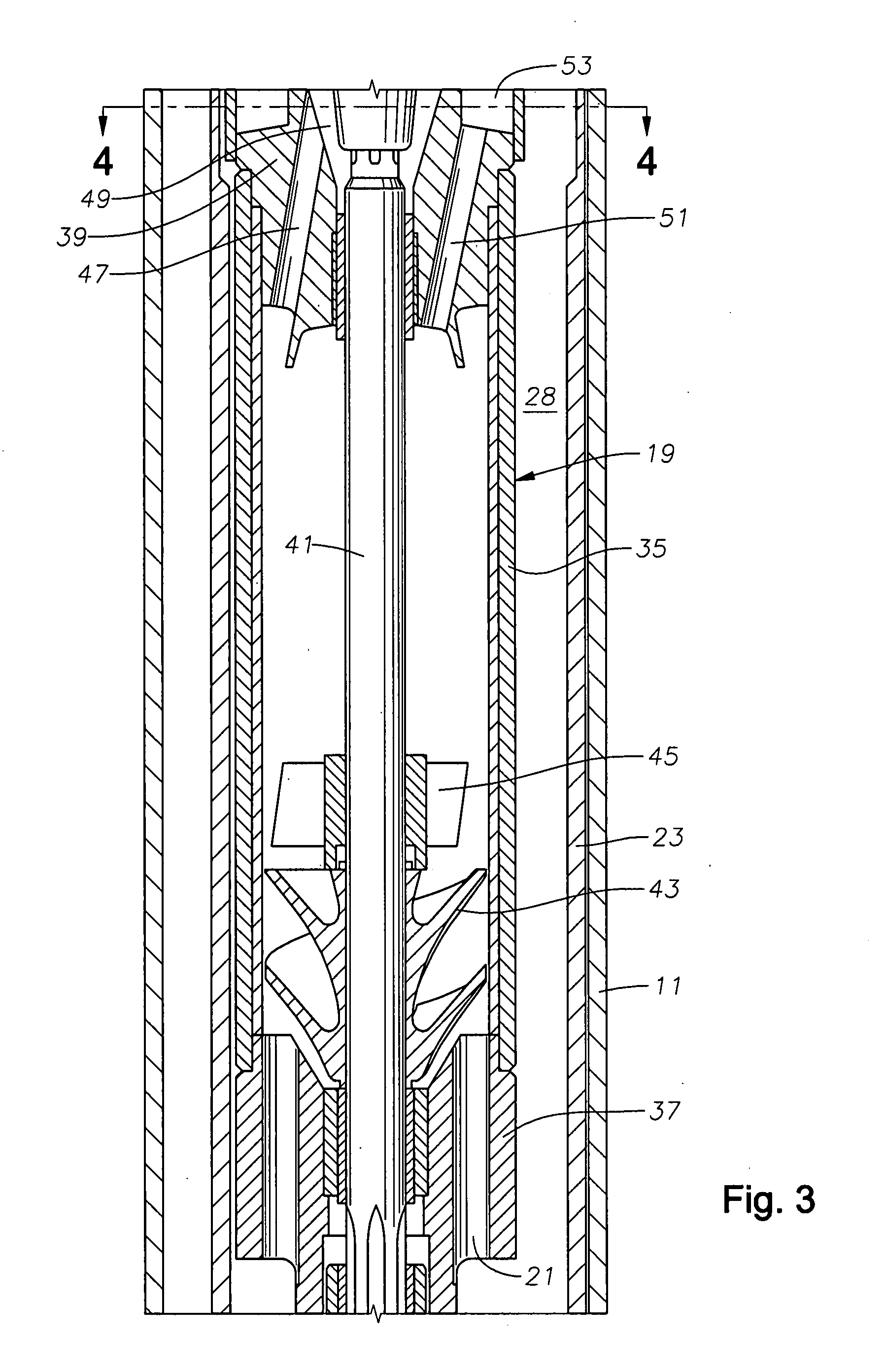
[0013]Referring to FIG. 1, cased borehole 11 illustrates a typical well having an inlet comprising perforations 13 for the flow of well fluid containing gas and liquid into cased borehole 11. A string of tubing 15 extends downward from the surface for supporting a rotary pump 17. Pump 17 is illustrated as being a centrifugal pump, which is one having a large number of stages, each stage having an impeller and a diffuser. Pump 17 could be other types of rotary pumps, such as a progressing cavity pump. A gas separator 19 is connected to the lower end of pump 17. Gas separator 19 is preferably an active type, as will be described subsequently. Gas separator 19 has an intake 21 through which all of the well fluid enters prior to reaching pump 17.

[0014]A shroud 23 is mounted in an inverted manner in the embodiment of FIG. 1. Shroud 23 has a closed lower end 25 that is secured sealingly around the pump assembly a short distance below gas separator intake 21. Shroud 23 has an open upper en...


PUM

PropertyMeasurementUnit
lengthaaaaaaaaaa
outer diameteraaaaaaaaaa
inner diameteraaaaaaaaaa

Abstract

A submersible well pump assembly has a gas separator that separates gas prior to entering into the pump. A shroud encloses a portion of the pump assembly, including the gas separator. The gas separator has gas discharge tubes that extend from it out through the shroud. The gas discharge tubes are tangentially aligned to create a vortex on the exterior of the shroud.

Description

FIELD OF THE INVENTION[0001]This invention relates in general to electrical submersible well pumps, and in particular to a submersible pump assembly enclosed by a shroud and having a gas separator therein that discharges gas tangentially from the shroud to initiate a vortex in the casing.BACKGROUND OF THE INVENTION[0002]An electrical submersible pump assembly (ESP) for a well typically includes a centrifugal pump driven by a submersible electrical motor. The ESP is normally installed within the well on tubing. Many wells produce a combination of oil and water as well as some gas. Centrifugal pumps are mainly designed to handle liquid and will suffer from head degradation and gas locking in the presence of a high percentages of free gas. Several techniques have been developed to remove the gas before it enters the pump.[0003]One technique relies on causing the well fluid to flow downward before reaching the pump intake to cause separation of gas. Gas bubbles within the well fluid flo...

Claims


Application Information

Patent Timeline
Patent Type & Authority Applications(United States)
IPC IPC(8): E21B43/40
CPCE21B43/38E21B43/128
Inventor BROWN, DONN J.WILSON, BROWN LYLEJAMES, GARY L.
Owner BAKER HUGHES INC
Features
  • Generate Ideas
  • Intellectual Property
  • Life Sciences
  • Materials
  • Tech Scout
  • Unparalleled Data Quality
  • Higher Quality Content
  • 60% Fewer Hallucinations
Learn More