Lighting control apparatus for vehicle
a technology for controlling apparatus and vehicle, which is applied in the direction of vehicle interior lighting, transportation and packaging, lighting circuits, etc., can solve the problems of system difficulty in assisting users to open doors or get into and out of vehicles, difficulty in being sufficiently illuminated, and insufficient illumination of the outside of the vehicl
- Summary
- Abstract
- Description
- Claims
- Application Information
AI Technical Summary
Benefits of technology
Problems solved by technology
Method used
Image
Examples
first embodiment
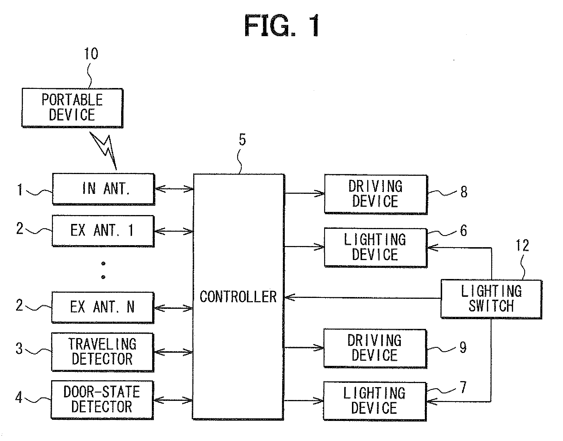
[0020]A lighting control apparatus according to a first embodiment of the invention will be described with reference to FIG. 1 and FIG. 2.
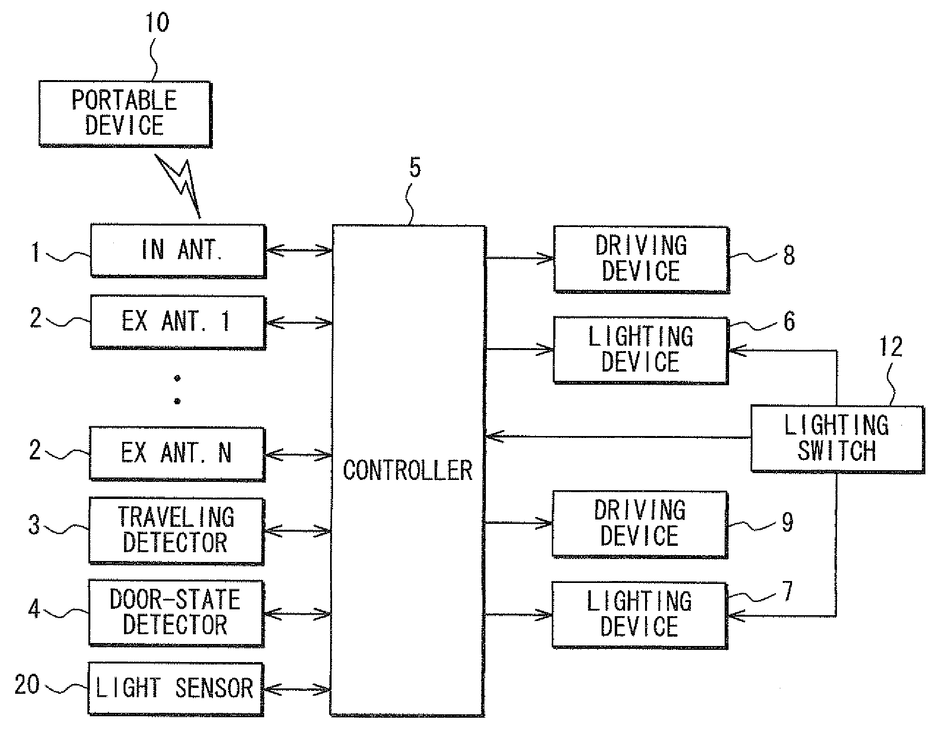
[0021]The lighting control apparatus includes an interior antenna (IN ANT) 1, a plurality of exterior antennas (EX ANT.1-EX ANT.N) 2, a traveling detector 3, a door-state detector 4, a controller 5, lighting device 6 and 7, and driving devices 8 and 9.
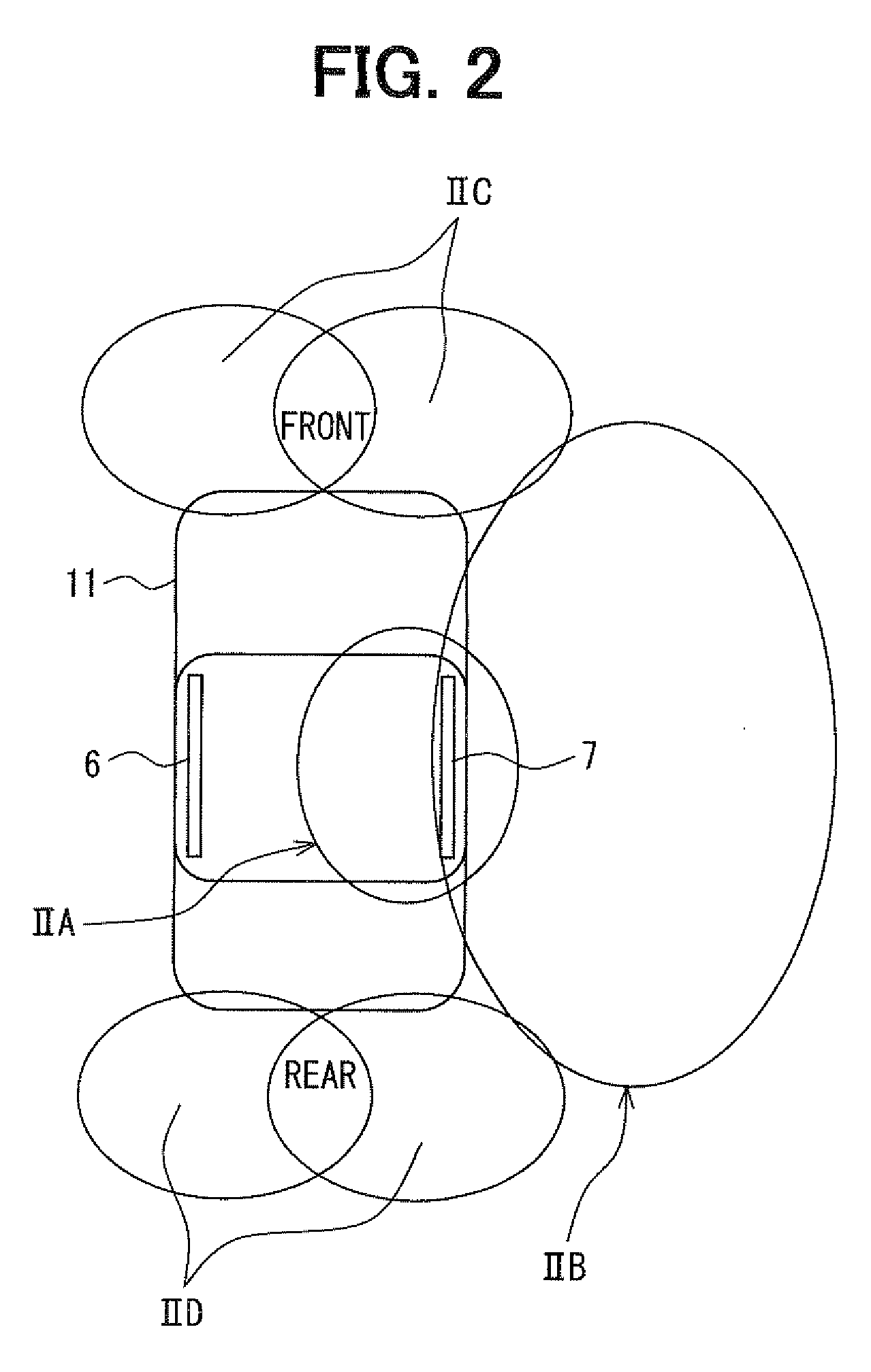
[0022]The interior antenna 1 and the exterior antennas 2 communicate with a potable device 10 for detecting whether a user having the portable device 10 is in a vehicle compartment, the user is in the vicinity of a vehicle 11, or the user is far from the vehicle 11. For example, each of the interior antenna 1 and the exterior antennas 2 sends a confirming signal to a communicating area thereof based on a command signal from the controller 5. When the portable device 10 is in one of the communicating areas and receives the confirming signal, the portable device 10 outputs a reply signal. The correspon...
second embodiment
[0040]A lighting control apparatus according to a second embodiment of the invention does not include the driving devices 8 and 9 provided in the lighting control apparatus according to the first embodiment. Other components in the present lighting control apparatus are similar to those in the lighting control apparatus according to the first embodiment.
[0041]As illustrated in FIG. 4 and FIG. 5, the lighting device 6 located on the left side of the roof includes a left first lighting element L1 for illuminating the inside of the vehicle compartment and a left second lighting element L2 for illuminating the outside of the vehicle compartment. The left first lighting element L1 and the left second lighting element L2 have different lighting directions. When the left first lighting element L1 is activated, the lighting device 6 can illuminate the inside of the vehicle compartment. When the left second lighting element L2 is activated the lighting device 6 can illuminate the outside of ...
third embodiment
[0043]In a lighting control apparatus according to a third embodiment of the invention, the left second lighting element L2 includes three lighting portions L2a-L2c, and the right second lighting element R2 includes three lighting portions R2a-R2c, as illustrated in FIG. 6
[0044]For example, the left second lighting element L2 of the lighting device 6 includes a first lighting portion L2a for illuminating a left front side of the vehicle 11, a second lighting portion L2b for illuminating a left side of the vehicle 11, and a third lighting portion L2c for illuminating a left rear side of the vehicle 11. The right second lighting element R2 of the lighting device 7 includes a first lighting portion R2a for illuminating a right front side of the vehicle 11, a second lighting portion R2b for illuminating a right side of the vehicle 11, and a third lighting portion R2c for illuminating a right rear side of the vehicle 11.
[0045]In this way, when each of the left second lighting element L2 ...
PUM
 Abstract
Description
Claims
Application Information
 - R&D
- Intellectual Property
- Life Sciences
- Materials
- Tech Scout
- Unparalleled Data Quality
- Higher Quality Content
- 60% Fewer Hallucinations
Browse by: Latest US Patents, China's latest patents, Technical Efficacy Thesaurus, Application Domain, Technology Topic, Popular Technical Reports.
© 2025 PatSnap. All rights reserved.Legal|Privacy policy|Modern Slavery Act Transparency Statement|Sitemap|About US| Contact US: help@patsnap.com


