
Ultrasonic Actuator

Inactive Publication Date: 2009-03-19
FUJI PHOTO OPTICAL CO LTD +1
View PDF9 Cites 2 Cited by
  • Summary
  • Abstract
  • Description
  • Claims
  • Application Information

AI Technical Summary

Benefits of technology

[0025]Providing a plurality of piezoelectric devices which sandwich the vibrator makes it possible to cause a large distortion of the vibrator so that the rotor can rotate fast, while avoiding an increase in size of the ultrasonic actuator.
[0036]According to the present invention, it is possible to provide a small ultrasonic actuator whose voltage control is easy.

Problems solved by technology

However, the image taking unit mounted in the small apparatus such as a portable telephone is so small that the unit has constraints on size of a charge-coupled device (CCD) and a lens as well as on space for accommodating them in the unit.
As a result, the small image taking unit has a difficulty in exhibiting a photographic function and an image quality equal to those of a digital camera.
Therefore, a use of the image taking unit is limited in photography in which a high image quality is not required, for example, a photograph substituted for a memorandum and a photograph for an image to be displayed on a stand-by screen of a portable telephone.
The remaining problem is to improve the shooting function.
But, an electro-magnetic motor consumes a lot of electricity and is rather large as a driving source.
Accordingly, mounting an electromagnetic motor on the small apparatus results in significant increase in size and weight of the small apparatus.
Moreover, mounting an electromagnetic motor requires an amount of electricity large enough to drive the electromagnetic motor in addition to the electricity used for other general photographic functions.
Therefore, it is difficult to mount zoom and autofocus functions by using an electromagnetic motor on a portable telephone and the like, which is required to be small and lightweight.
Therefore, these techniques have such a problem that the voltage control becomes complex.
The above problems are not limited to image taking units, but they occur in any field in which an ultrasonic actuator driven by application of a voltage is used.

Method used


Image

  • Ultrasonic Actuator
  • Ultrasonic Actuator
  • Ultrasonic Actuator

Examples


Embodiment Construction

[0051]First of all, the above-described problems in a conventional ultrasonic actuator making use of piezoelectricity will be analyzed in detail.

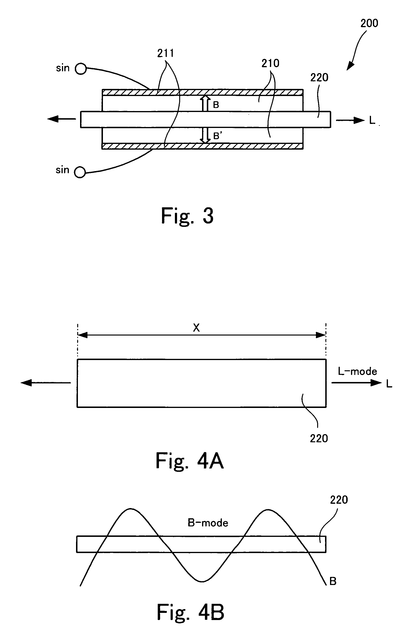
[0052]FIG. 3 is an explanatory diagram of a principle on which a conventional ultrasonic actuator operates.

[0053]As shown in FIG. 3, the ultrasonic actuator 200 basically includes a metallic vibration plate 220, two piezoelectric devices 210 sandwiching the vibration plate 220, and electrodes 211 to apply a voltage to the piezoelectric devices 210. The piezoelectric devices 210 are polarized in the directions of an arrows B and B′, respectively, along thickness of the piezoelectric devices 210 which is perpendicular to the vibration plate 220. The vibration plate 220 serves as a vibrating object which is distorted by vibration of the piezoelectric devices. In addition, the vibration plate 220 also serves as a counter electrode with respect to the electrodes 211. Besides various components shown in FIG. 3, there are: a holding member which h...


PUM


Abstract

It is an object to provide a small ultrasonic actuator whose voltage control is easy. The ultrasonic actuator acts on a rotatable rotor to rotate the rotor, the ultrasonic actuator includes: a plate vibrator having one end which contacts the rotor, a corner portion bent at a midpoint in the vibrator, and the other end which is fixed; and a piezoelectric device which contacts a part of the vibrator between the one end and the corner portion, and transmits a vibration to the vibrator by vibrating in response to application of an alternating voltage between one of electrodes provided respectively on both surfaces or the plate vibrator serving as the one of the electrodes and the other of the electrodes.

Description

TECHNICAL FIELD[0001]The present invention relates to an ultrasonic actuator which acts on a rotatable rotor to rotate the rotor.BACKGROUND ART[0002]Recent small apparatuses such as a portable telephone have a built-in image taking unit for shooting an image of a subject. As a user of such a small apparatus need not carry a digital camera or a video camera in order to take a photograph, he / she can always take a photograph easily. Also, such a small apparatus generally is provided with a data communications capability using radio or infrared rays. Thus, such a small apparatus has another advantage that a user can send image data to another portable telephone or a personal computer immediately after shooting.[0003]However, the image taking unit mounted in the small apparatus such as a portable telephone is so small that the unit has constraints on size of a charge-coupled device (CCD) and a lens as well as on space for accommodating them in the unit. As a result, the small image takin...

Claims


Application Information

Patent Timeline
IPC IPC(8): H02N2/12
CPCH02N2/103H02N2/003
Inventor ISHIGURO, MINORUYAMAMOTO, SHINICHIAOYAGI, MANABU
Owner FUJI PHOTO OPTICAL CO LTD
Learn More