Folding Table and Support Frame Assembly

a support frame and folding table technology, applied in the field of tables, can solve the problems of not enlarge the table surface, user's inability to minimize the table surface, and may not provide sufficient space for resting and using service items on the surface,

Active Publication Date: 2009-03-26
AMERICAN HONDA MOTOR COMPANY
View PDF24 Cites 69 Cited by
  • Summary
  • Abstract
  • Description
  • Claims
  • Application Information

AI Technical Summary

Benefits of technology

[0014]In another aspect, the frame assembly provides support to a table and is movably connected to the table. The table comprises a distal portion, a hinging member movably connected to the distal member by a first rod, and a proximal member movably connected to the hinging member by a second rod and movably connected to the frame assembly. The table and frame assembly adjusts to a stowed position, partially extended position, and a fully extended position. The hinging member enables a foldable relationship between the distal portion and the proximal member to achieve the partially extended position and the fully extended position. The hinging member functions as a handle when moving the table and frame assembly between the stowed position and the partially extended position.

Problems solved by technology

If the table surface was too small, a user could not enlarge the table surface to obtain a larger work area.
If the table surface was too large, a user could not minimize the table surface to conserve space for other activities or to move about.
These surfaces may not provide sufficient space for resting and using service items, games, books, computers, and papers.
This particular design may also make it difficult for individuals to move the table from the stowed position to an extended position.
The surface is also limited by the relatively small size of the side of a chair.
Sometimes these features cause the user's fingers, clothes, and other items to snag.
This may result in pain and damage to the user and his possessions.
Certain folding tables also were difficult to remove from their stowed position or had crude mechanisms to remove the table from the stowed position.
These folding tables lacked handles and used clumsy mechanical linkages.

Method used


Image

  • Folding Table and Support Frame Assembly
  • Folding Table and Support Frame Assembly
  • Folding Table and Support Frame Assembly

Examples


Embodiment Construction

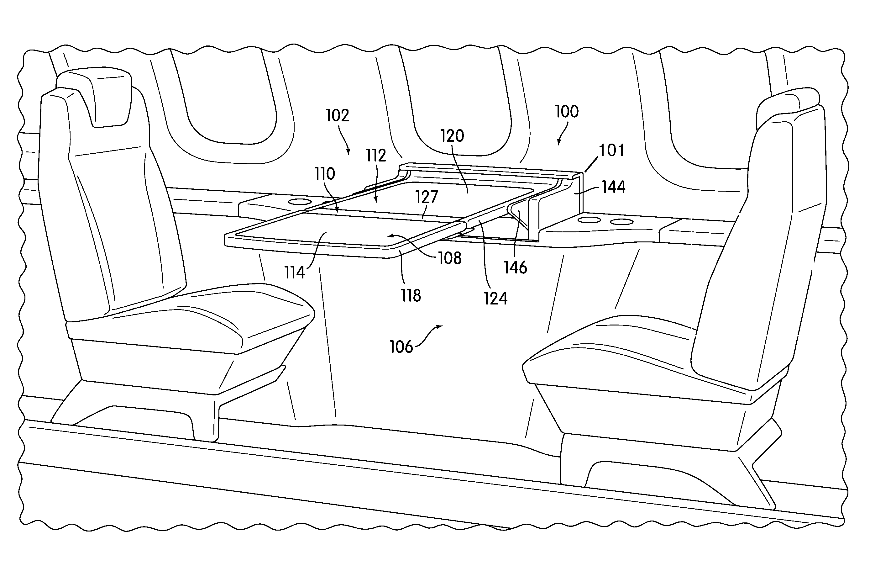
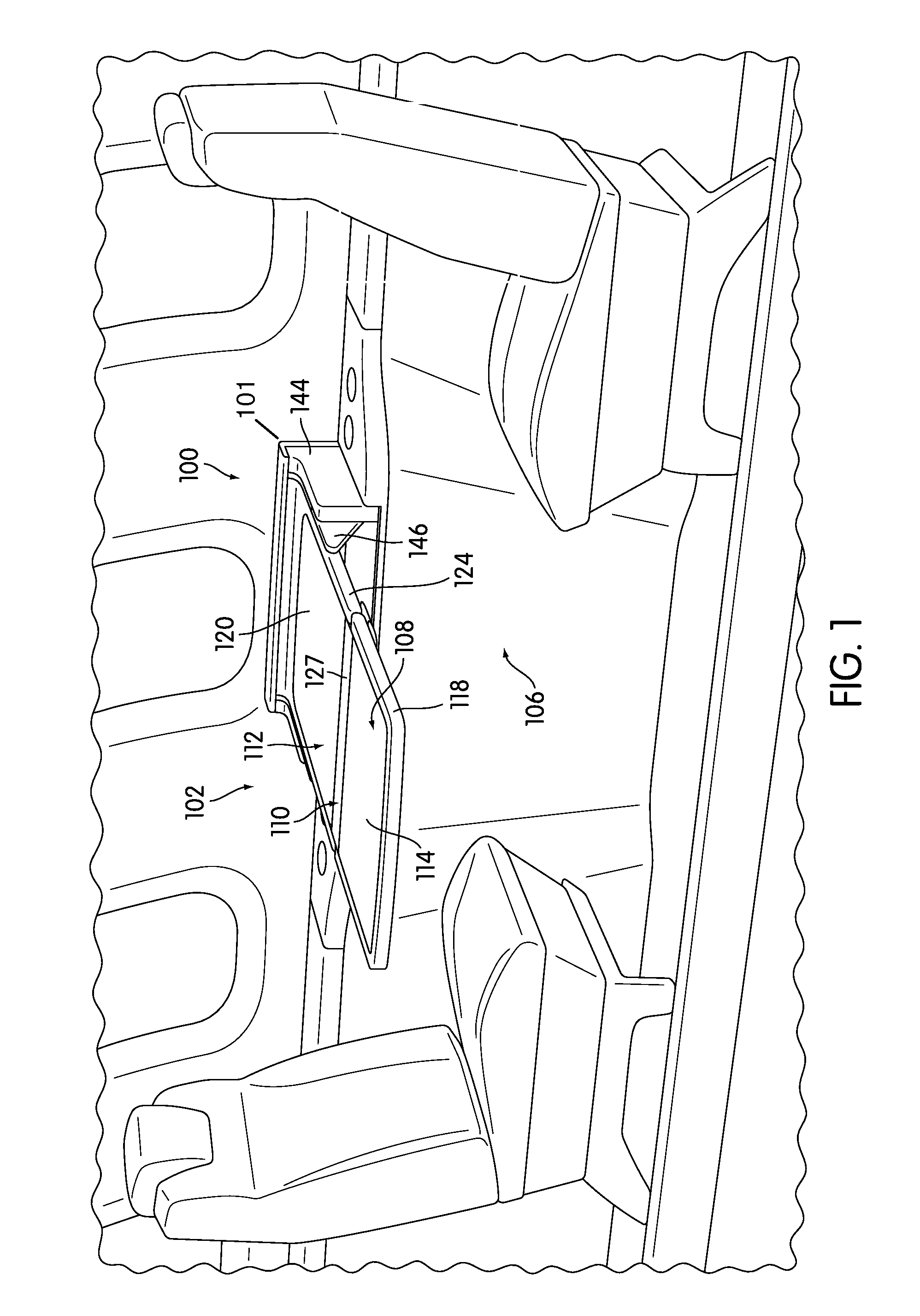
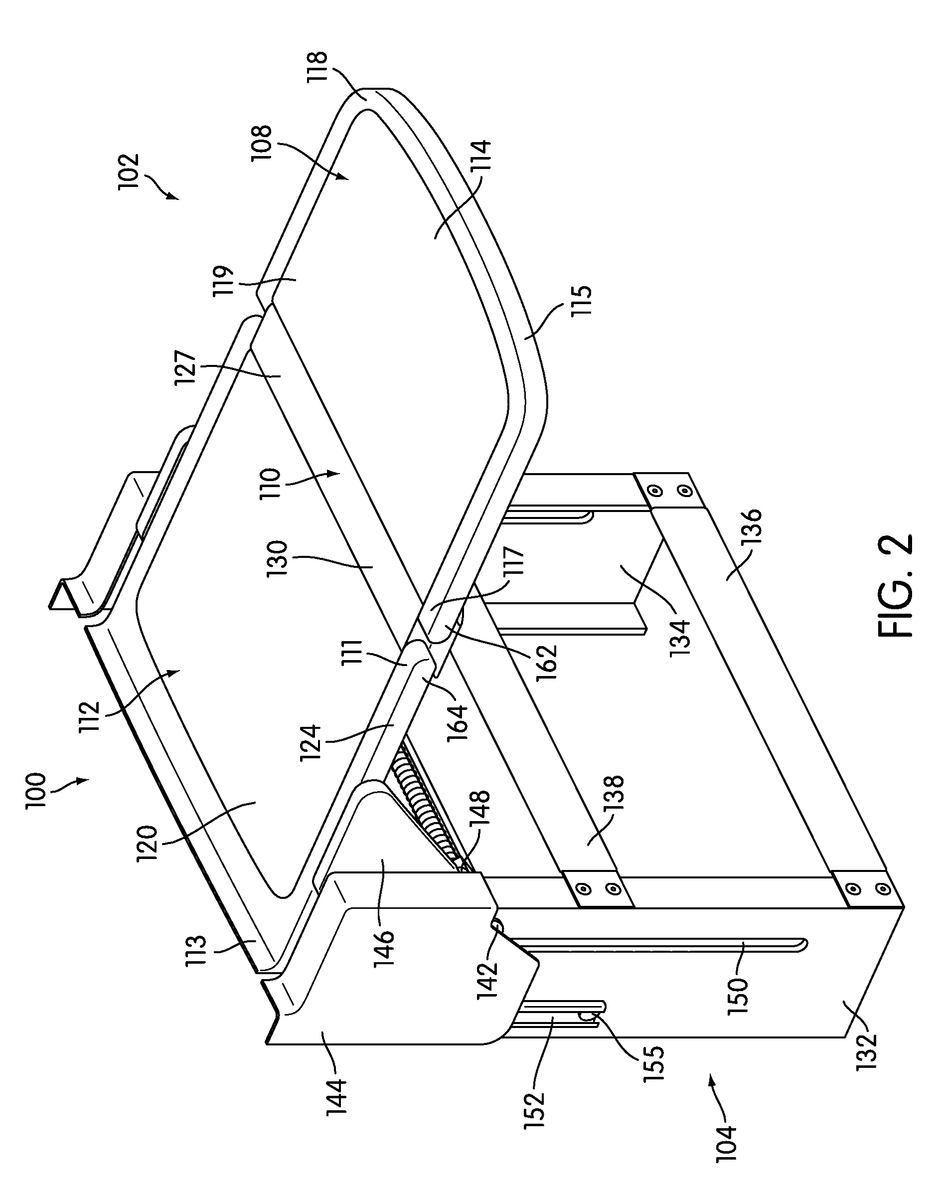
[0033]Embodiments of the present invention are first described using FIGS. 1-6 that illustrate a folding table and support frame assembly in operation. Then the invention is described using FIGS. 2-15 to illustrate the folding table and support frame assembly in more detail. With respect to FIGS. 1-15, for convenience of description various features may be referred to as the top end, bottom end, top portion, and bottom portion and various directions may be referred to as down or up. These descriptions referring to the orientation of the device as illustrated in the drawings are for convenience and clarity, and should not be interpreted as limiting the scope of the invention in any way. It is understood that directional adjectives will change if the device were viewed from a different orientation than as pictured

[0034]FIG. 1 is a schematic environmental diagram of a preferred embodiment of a folding table assembly in an extended position. Referring to FIG. 1, folding table assembly 1...


PUM


Abstract

A folding table and support frame assembly is disclosed. The table comprises two planar portions connected by a hinging member. One of the planar portions is coupled to a support frame such that the folded table can be moved into a stowed position within the support frame assembly. The planar portions comprise a proximal portion or inner member and a distal portion or outer member. The proximal portion and distal portion are connected to one another by the hinging member or middle member. The hinging member enables the rotation of the distal portion into a folded relationship upon the proximal portion. When the two planar portions are folded, they provide a smaller table surface in a half-open or partially extended position. When the two planar portions are opened along the hinging member, the planar portions and the hinging member provide a larger contiguous table in the fully extended position.

Description

CROSS REFERENCE TO RELATED APPLICATIONS[0001]This application is a continuation in part of U.S. application Ser. No. 29 / 295,082, entitled “Folding Table”, and filed on Sep. 21, 2007, which patent application is hereby incorporated by reference in its entirety.BACKGROUND OF THE INVENTION[0002]1. Field of the Invention[0003]The present invention relates generally to tables, and more specifically to a folding table and support frame assembly that can be used as a horizontal table surface in multiple positions and further folded to be stowed.[0004]2. Description of Related Art[0005]Stowable table surfaces have been used in a variety of environments including vehicles, living areas, lecture halls, and chairs. For example, stowable tray tables are used on airplanes, desks are equipped with stowable table surfaces, and stowable tables are used on recreational vehicles. They are particularly useful when space is at a minimum. The table can be extended when a table surface is needed and then...

Claims


Application Information

Patent Timeline
Patent Type & Authority Applications(United States)
IPC IPC(8): A47B3/00A47B1/04
CPCA47B5/006B64D11/0638B61D37/00B60N3/007
Inventor OSBORNE, CHRISMICHAEL, TSAY
Owner AMERICAN HONDA MOTOR COMPANY
Why Eureka
Try Eureka