AI technical title is built by Patsnap AI team. It summarizes the technical point description of the patent document.
a technology of spacer grid and apparatus, which is applied in the direction of manufacturing tools, nuclear engineering, nuclear elements, etc., can solve the problems of spacer grid, spacer grid welding defect, defective material,
Active Publication Date: 2009-04-02
KEPCO NUCLEAR FUEL CO LTD
View PDF16 Cites 8 Cited by
Summary
Abstract
Description
Claims
Application Information
AI Technical Summary
This helps you quickly interpret patents by identifying the three key elements:
Problems solved by technology
Method used
Benefits of technology
Benefits of technology
The present invention provides a laser welding apparatus that can capture images of a spacer grid simultaneously with a welding task to determine whether to perform a welding task again by immediately checking a welding state after welding. The apparatus can also minimize the hot spot phenomenon and store the image of the spacer grid when the pulse laser generator is in an off state. The apparatus includes a pulse laser generator, a servomotor, a beam splitter, an image sensor, welding control means, a servo motor, a beam splitter, an image sensor, and welding control means. The image sensor can sense and store the image of the spacer grid when the pulse laser generator is in an off state. The apparatus can also include a welding state determination means and an attenuation filter to improve the accuracy of welding state detection.
Problems solved by technology
It has been known that defects of a spacer grid during its fabrication includes defective material of plates constituting a spacer grid, fixing defects of plates before welding, laser defects upon welding, fixing defects of retention straps for fixing plates constituting a spacer grid upon welding task, and so on.
It has been known that if the several defects occur in combination, it results in welding defects of the spacer grid.
Thus, the entire welding spots are not formed regularly and have some error.
However, this method is problematic in that the time taken before the welding task of the spacer grid is lengthened and it cannot cope with welding defects immediately, thereby decreasing work efficiency.
It makes it difficult to read the image.
Method used
Image
Click on the blue label to locate the original text in one second.
Reading with bidirectional positioning of images and text.
Examples
embodiment 1
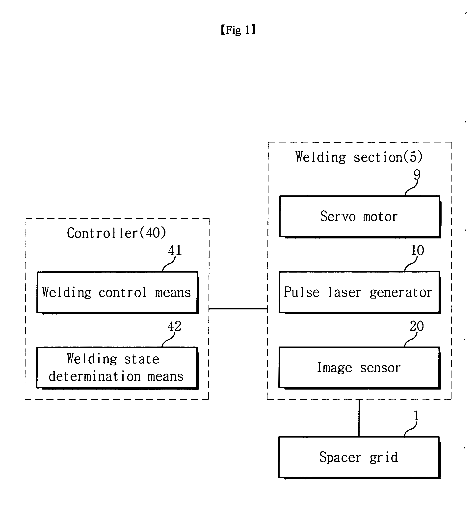
[0030]FIG. 1 is a block diagram showing an overall construction of a laser welding apparatus according to the present invention.
[0031]Referring to FIG. 1, the laser welding apparatus according to the present embodiment can be largely divided into a controller 40 and a welding section 5.
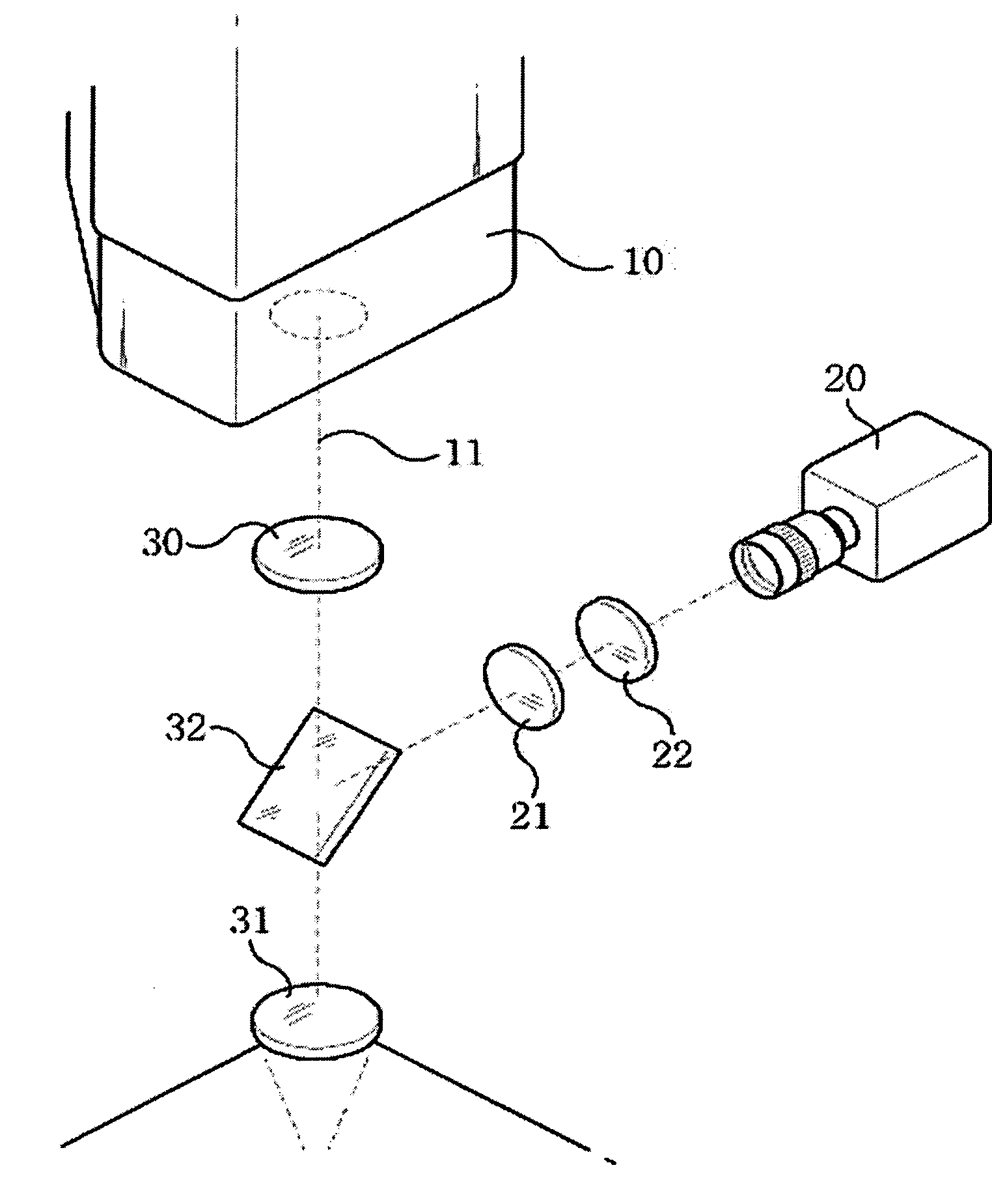
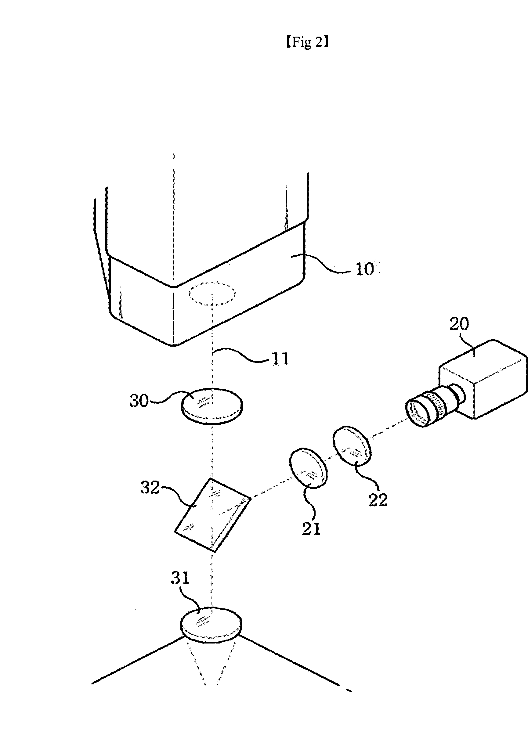
[0032]The welding section 5 will be first described hereinafter with reference to FIGS. 1 and 2.
[0033]The welding section 5 includes a beam splitter, an image sensor, an attenuation filter and a bandpass filter as well as the known laser welding apparatus including a servo motor, a pulse laser generator, a collimation lens and a focus lens.
[0034]The servo motor, as known in the art, functions to move the welding section 5 on the X-Y plane.
[0035]A laser for welding a spacer grid may employ a laser of a pulse form in which an on state and an off state are repeated, as shown in FIG. 4, in order to sufficiently secure a welding depth and prevent welding defect. It is assumed that a laser of the present em...
embodiment 2
[0051]An embodiment 2 differs from the embodiment 1 in an image acquisition method of the image sensor 20.
[0052]In the embodiment 1, an image is preferably stored during the low-temperature period (the last 17 ms period of the off-time). In the embodiment 2, however, a consecutive image is captured during off-time, an image distortion phenomenon caused by hot spots is sensed, and when the distortion phenomenon is less than a reference value, a corresponding frame is stored as an image.
[0053]From the constructions of the present invention, the welding method of the present invention can shorten an initial time taken for a welding task and improve work efficiency.
[0054]Further, according to the welding method of the present invention, images captured during a welding task are provided in order to immediately determine a welding state. Accordingly, the effort and time taken to check a welding state after welding can be saved and, therefore, an overall work efficiency can be improved.
[0...
PUM
Property
Measurement
Unit
wavelength range
aaaaa
aaaaa
temperature
aaaaa
aaaaa
frequency
aaaaa
aaaaa
Abstract
The present invention relates to an apparatus and method for capturing an image of a welding spot during a welding task and determining an accurate position of the welding spot based on the captured image in order to perform an accurate welding task. A beam splitter splits a path of light reflected from a welding section of a spacer grid from a path of a laser beam generated from a laser generator. An image sensor receives light reflected from a welding spot of the spacer grid, and senses and stores an image of the spacer grid. Welding control means controls the image sensor to capture the image of the spacer grid, receives the image of the spacer grind from the image sensor, calculates an accurate position of the welding spot based on the received image, corrects position information of the welding spot based on the calculated position, and controls a servo motor so that the laser generator can accurately collimate the welding spot based on the corrected position value.
Description
BACKGROUND OF THE INVENTION[0001]1. Field of the Invention[0002]The present invention relates to an apparatus for and method of welding a spacer grid, and more particularly, to an apparatus and method for capturing an image of a welding spot during a welding task and determining an accurate position of the welding spot based on the captured image in order to perform an accurate welding task.[0003]2. Background of the Related Art[0004]In recent years, a spacer grid used to support and fix a nuclear fuel is formed in a lattice shape by intersecting long plates, which are generally made of zirconium, vertically and horizontally and then performing welding, as disclosed in Korean Patent Application No. 10-1983-0004399. More specifically, each of the plates has grooves formed therein for accommodating the plates that cross each other at right angles. The grooves are fixed in such a manner that they are coupled to one another, and intersections of the plates that cross each other at right...
Claims
Application Information
Patent Timeline
Application Date:The date an application was filed.
Publication Date:The date a patent or application was officially published.
First Publication Date:The earliest publication date of a patent with the same application number.
Issue Date:Publication date of the patent grant document.
PCT Entry Date:The Entry date of PCT National Phase.
Estimated Expiry Date:The statutory expiry date of a patent right according to the Patent Law, and it is the longest term of protection that the patent right can achieve without the termination of the patent right due to other reasons(Term extension factor has been taken into account ).
Invalid Date:Actual expiry date is based on effective date or publication date of legal transaction data of invalid patent.
Patent Type & AuthorityApplications(United States)

