
Radiographic marker for inclination angle

Inactive Publication Date: 2009-04-02
CARESTREAM HEALTH INC
View PDF16 Cites 1 Cited by
  • Summary
  • Abstract
  • Description
  • Claims
  • Application Information

AI Technical Summary

Benefits of technology

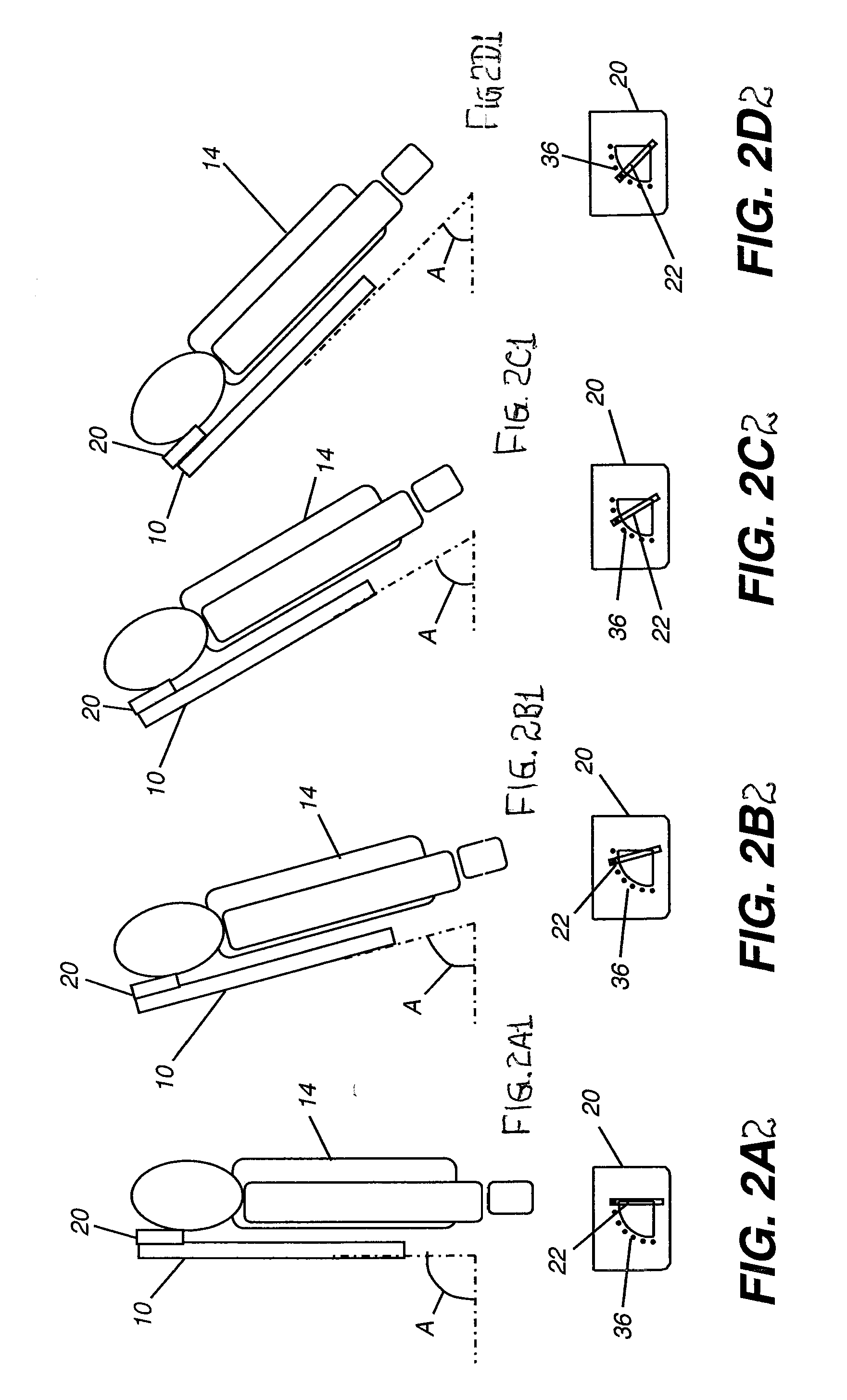
[0007]An advantage of the disclosed radiographic marker is that it provides an intuitive device for indicating inclination angle of a radiographic receiver. The marker can be positioned along an edge of the receiver and manually set to a suitable position by the operator.

Problems solved by technology

While there have been a number of different devices and methods proposed for showing the inclination angle of the patient during exposure, however, these have not been widely adopted for a number of reasons.
Some of these devices and methods are relatively complex, such as the device described in the Collin et al.
Others, such as the Greenberg '548 device, can be bulky and cumbersome to use.

Method used


Image

  • Radiographic marker for inclination angle
  • Radiographic marker for inclination angle
  • Radiographic marker for inclination angle

Examples


Embodiment Construction

[0016]The present description is directed in particular to elements forming part of, or cooperating more directly with, a radiographic marker. It is to be understood that elements not specifically shown or described may take various forms well known to those skilled in the art.

[0017]The disclosed radiographic marker can be used with any of the available types of radiographic receivers. Compatible receiver types include, but would not be limited to, sensitized film or other photostimulable medium, a computed radiography (CR) plate, or a direct radiography (DR) detector. The marker is intended to be used where ionizing radiation, such as x-ray radiation, is used to produce a diagnostic image. The Figures are provided to show overall composition, function, and use of the marker and are not drawn with attention to scale. It is to be understood that any number of additional embodiments are possible, as defined by the claims.

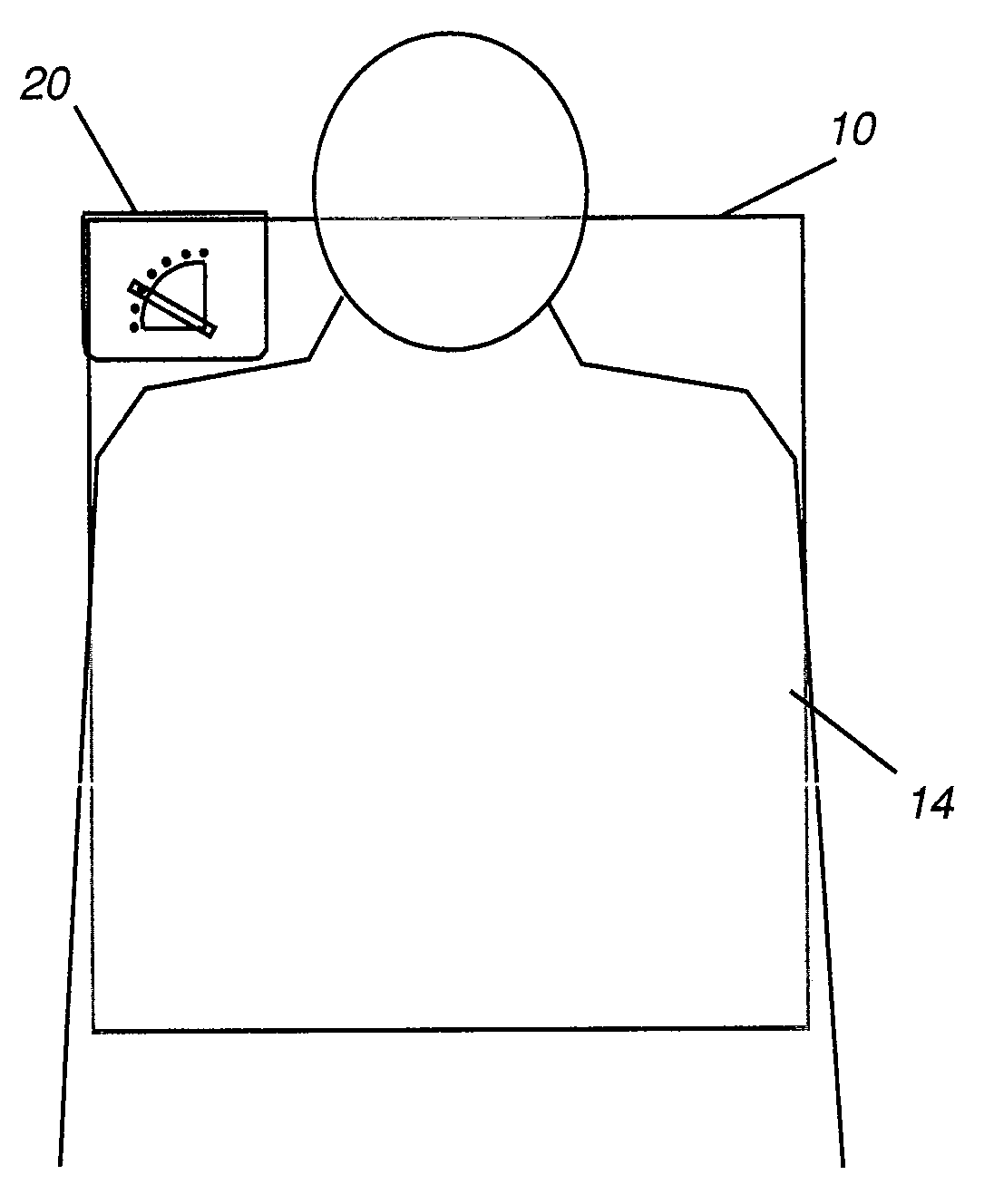
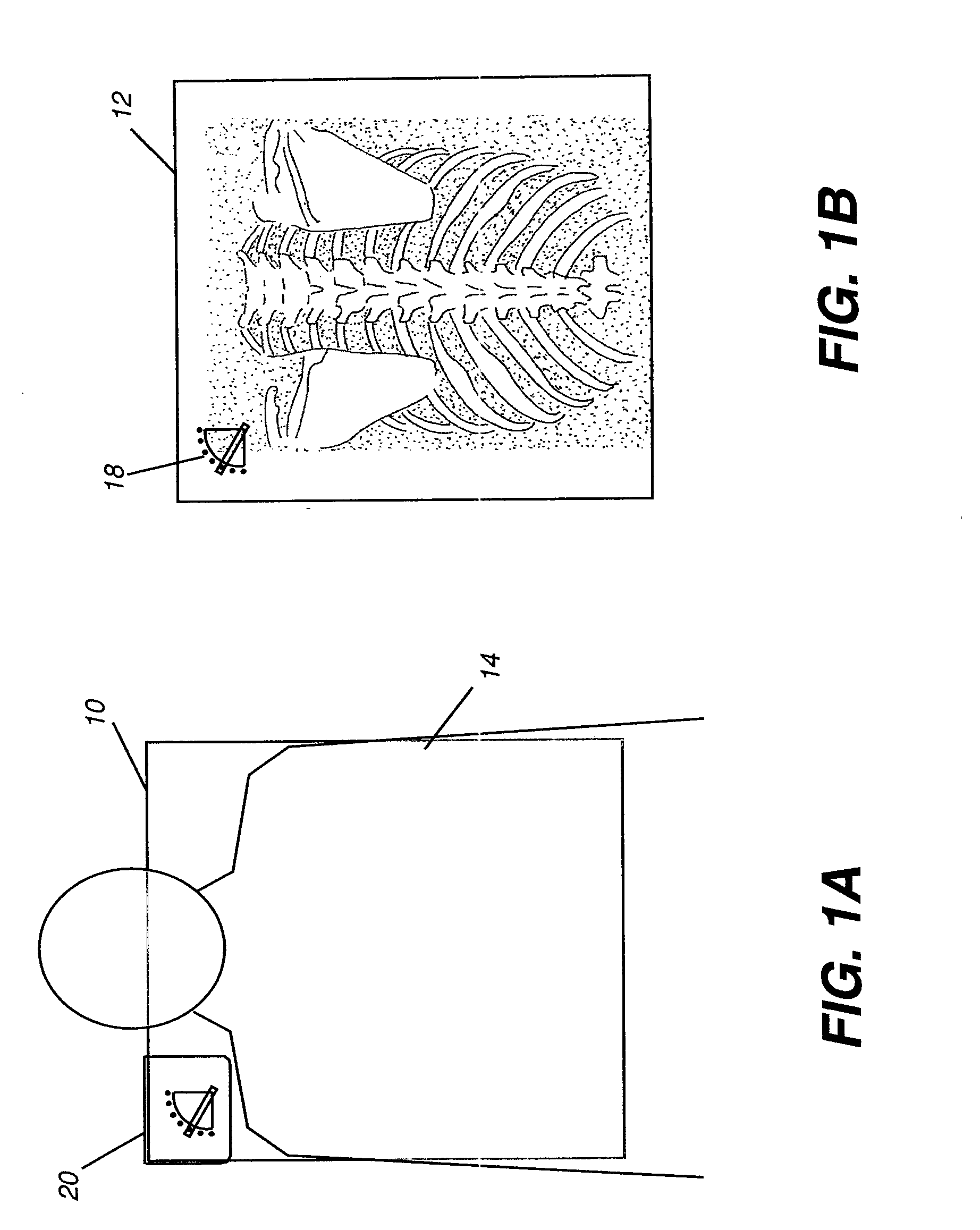
[0018]FIG. 1A shows one embodiment of radiographic marker 20 of ...


PUM


Abstract

A radiography marker for indicating the inclination angle of a radiography receiver has a plate portion defining at least one area transparent to radiation and an angle indicator element attached to the plate portion at a pivot point and adjustable along the plate portion to any of a plurality of angular positions over at least a portion of the at least one area transparent to radiation. At least a portion of the indicator element is radio-opaque.

Description

FIELD OF THE INVENTION[0001]This invention generally relates to radiographic imaging and more particularly relates to a marker for indicating inclination angle of a radiographic imaging receiver.BACKGROUND OF THE INVENTION[0002]A number of different types of radiographic markers have been developed and used to support the radiographic imaging process. For example, markers indicating “L” or “R” may be used to identify left or right areas or sections of the body that appear on the image. Other markers can identify the patient, doctor, or radiologic technician, date, imaging facility, and other information. Markers can also be used to show the orientation of the exposed area. To use a marker, the technician sets up the patient for imaging and places one or more markers in an area of the film or other type of receiver that will receive exposure energy but where the marker does not interfere with the diagnostic image content. Just a few illustrative examples of some types of Left / Right m...

Claims


Application Information

Patent Timeline
IPC IPC(8): G03B42/02
CPCG03B42/02
Inventor WANG, XIAOHUIFOOS, DAVID H.
Owner CARESTREAM HEALTH INC
Learn More