Spectacle frame bridge housing electronics for electro-active spectacle lenses

Inactive Publication Date: 2009-04-23
DUSTON DWIGHT P +4
View PDF99 Cites 39 Cited by
  • Summary
  • Abstract
  • Description
  • Claims
  • Application Information

AI Technical Summary

Problems solved by technology

These lenses present new challenges in aesthetically packaging and integrating the electronics within a fashionable spectacle lens frame.

Method used


Image

  • Spectacle frame bridge housing electronics for electro-active spectacle lenses
  • Spectacle frame bridge housing electronics for electro-active spectacle lenses
  • Spectacle frame bridge housing electronics for electro-active spectacle lenses

Examples


first embodiment

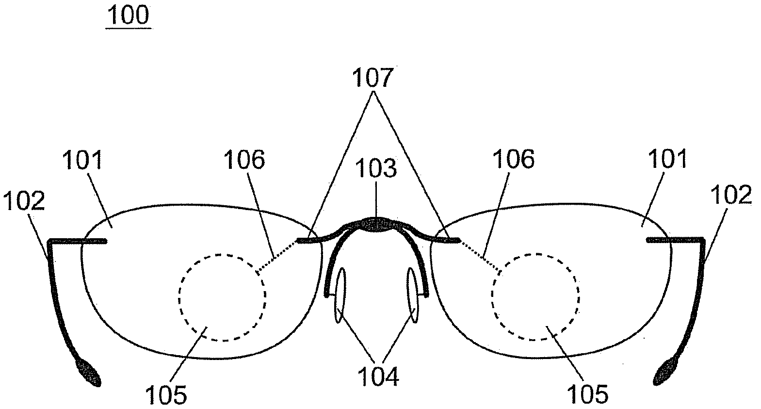
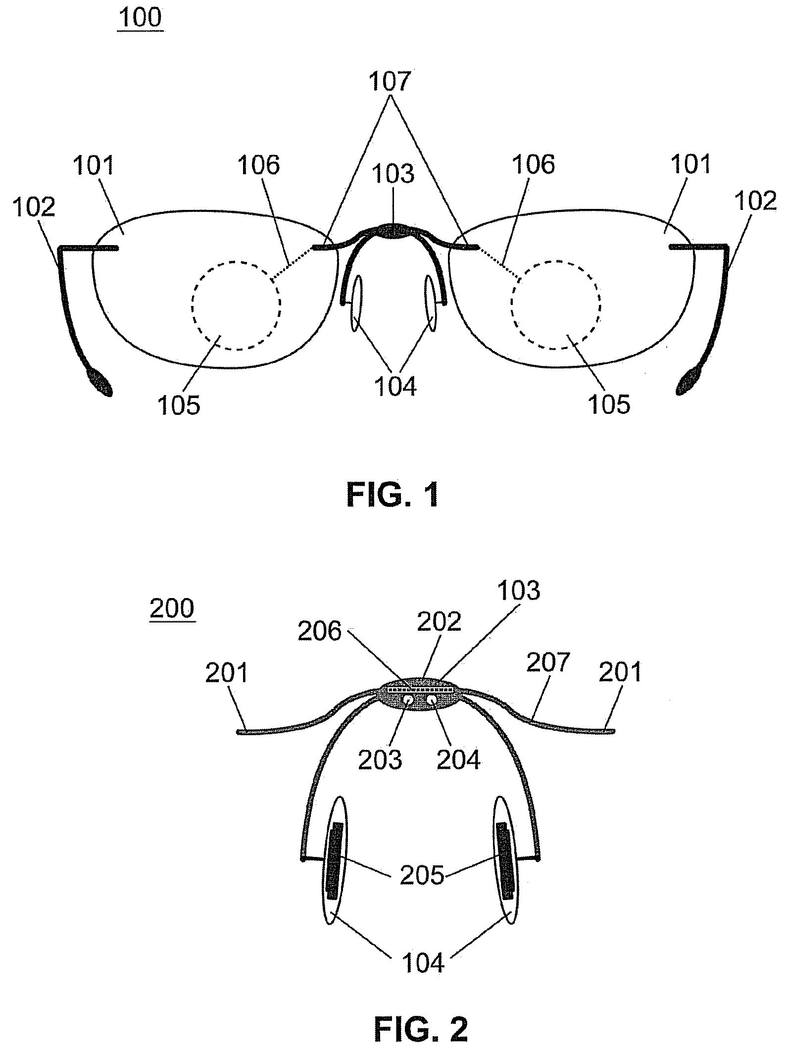
[0036]In nose bridge 103 shown in FIG. 2, nose bridge 200 is a self-contained unit that is designed to be compatible with many different types of spectacle frames. For example, nose bridge 200 may be used with front eye-wire style spectacle frames and the like. At least a portion of the electronic components and circuitry are concealed within the body 202 of the nose bridge 200. Electrical connection to the electro-active portion of the lenses 105 may be made by means of connecting element 207. Connecting element 207 selves to mechanically and electrically connect the body 202 of nose bridge 200 to lenses 101. Connecting element 207 contains electrical contact points 201, which are located at the points where the bridge connects to lenses 101.

[0037]Electro-active lenses may require input from the wearer's environment to operate properly. For example, it may be beneficial to detect the distance to which a wearer is focused by means of a range finding or view detecting device and adju...

second embodiment

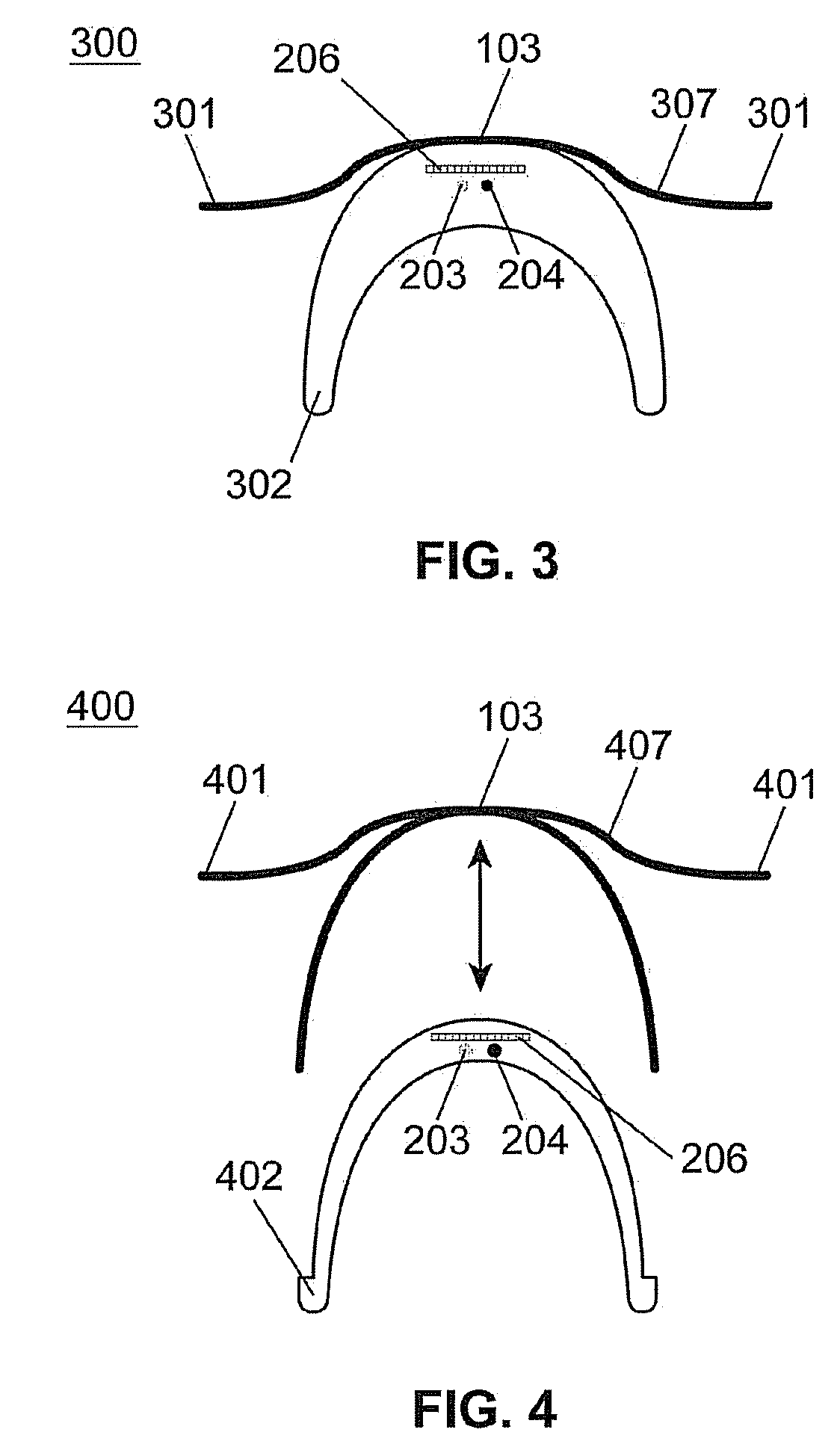
[0040]In nose bridge 103 shown in FIG. 3, nose bridge 300 is primarily comprised of a body 302 which contains at least a portion of the electronic components and circuitry. Body 302 may be molded from an organic resin(s). Electrical connection to the electro-active portion of the lenses 105 is made by means of connecting element 307. Connecting element 307 serves to mechanically and electrically connect the body 302 of nose bridge 300 to lenses 101. Connecting element 307 contains electrical contact points 301, which are located at the points where the bridge connects to lenses 101. Power source 205 may be encapsulated within the bridge body 302 in which case it may be rechargeable. Alternately, body 302 may open to allow the removal and replacement of power source 205. Molded body 302 may contain a transmitter 203 and / or a receiver 204 for sensing the wearer's environment. Molded body 302 may also contain a photovoltaic array 206 for providing extra electrical power or for rechargi...


PUM


Abstract

A nose bridge for a fashion spectacle lens frame adapted for housing electro-active lenses is presented. The nose bridge may include a body which may further include electronic components. The nose bridge may further include a connecting element for connecting the electronic components with the electro-active lenses for altering optical properties of the electro-active lenses. The nose bridge may be adapted to fit a variety of frame sizes, shapes, and styles as well as lenses of a variety of sizes and shapes.

Description

CROSS REFERENCE TO RELATED APPLICATIONS[0001]This application claims priority from and incorporates by reference in its entirety provisional application U.S. Ser. No. 60 / 796,876, titled “Spectacle Frame Bridge Housing Electronics for Electro-Active Spectacle Lenses”, filed on May 3, 2006.[0002]This application is a Divisional Application of copending application Ser. No. 11 / 797,210.[0003]This application is also a continuation-in-part of co-pending U.S. patent application Ser. No. 11 / 321,324, titled “Ophthalmic Lens for Correcting Non-Conventional Refractive Error”, filed on Dec. 29, 2005, which is hereby incorporated by reference in its entirety and which is, in turn, a continuation of U.S. patent application Ser. No. 11 / 091,104, titled “System, Apparatus, and Method for Correcting Vision Using an Electro-Active Lens”, filed on Mar. 28, 2005, which is, in turn, a continuation of U.S. patent application Ser. No. 10 / 626,973, titled “System, Apparatus, and Method for Correcting Vision...

Claims


Application Information

Patent Timeline
Patent Type & Authority Applications(United States)
IPC IPC(8): G02C7/08G02C11/00
CPCG02C5/02G02C2202/20G02C7/101G02C7/083
Inventor DUSTON, DWIGHT P.BLUM, RONALD D.HADDOCK, JOSHUA N.KOKONASKI, WILLIAMIYER, VENKATRAMANI S.
Owner DUSTON DWIGHT P
Why Eureka
Try Eureka