
Method for determining positions of structures on a substrate

Active Publication Date: 2009-04-30
VISTEC SEMICON SYST
View PDF15 Cites 0 Cited by
  • Summary
  • Abstract
  • Description
  • Claims
  • Application Information

AI Technical Summary

Benefits of technology

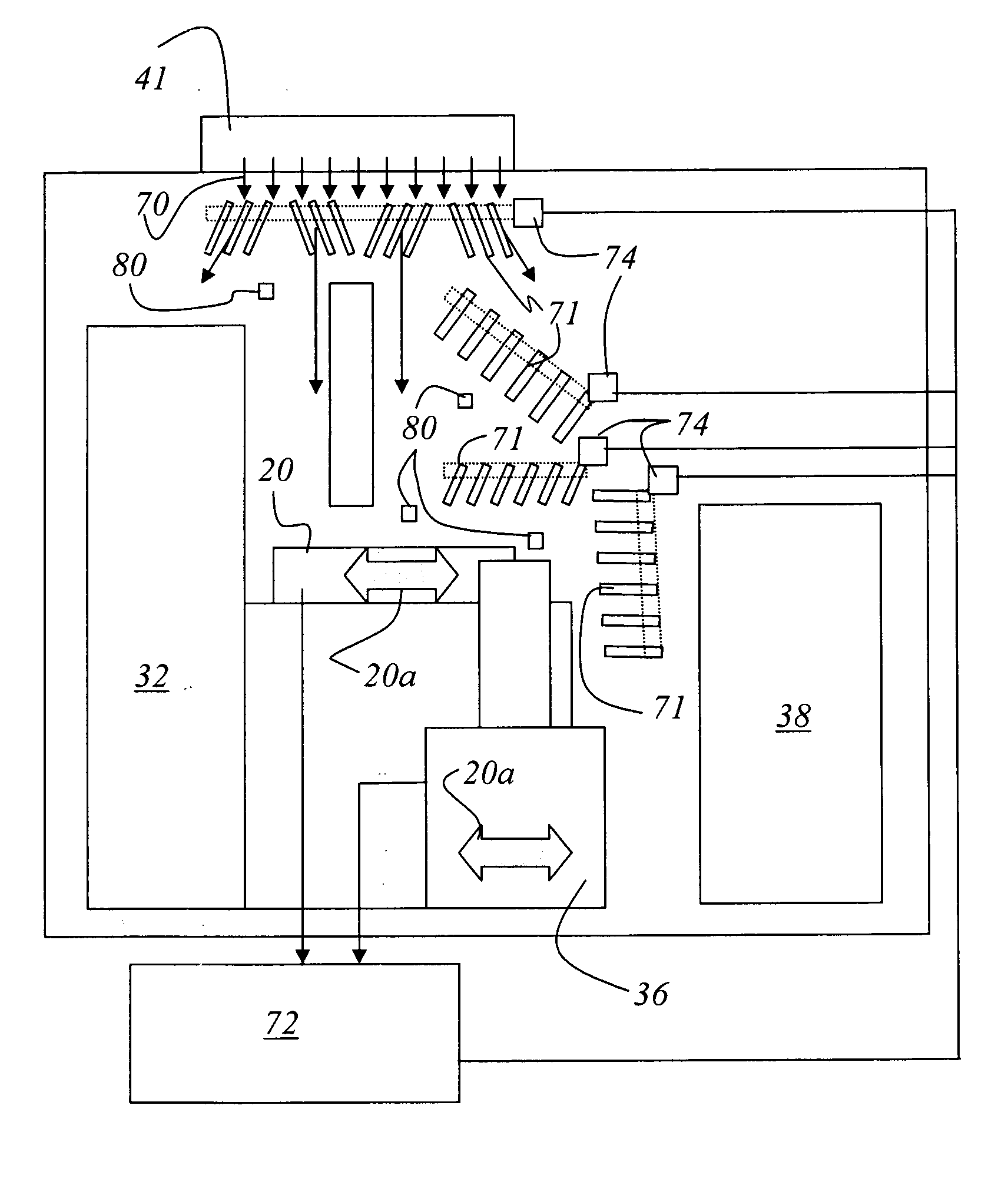
[0013]It is particularly advantageous if the air-directing elements are motor-adjustable air-directing plates which may be adjusted depending on the position of the at least one movable station such that the invariable flow is ensured. The air-directing plates are arranged in at least part of the flow in the housing. The air-directing element may further be designed as adjustable collar arranged around the measurement table. Depending on the position of the movable station (measurement table or transport robot), the collar may be adjusted such that an invariable flow is ensured.

Problems solved by technology

Since there may also be movable stations in the housing (measurement table, transport unit), the air flow may be disturbed due to the movement of the movable stations.

Method used


Image

  • Method for determining positions of structures on a substrate
  • Method for determining positions of structures on a substrate
  • Method for determining positions of structures on a substrate

Examples


Embodiment Construction

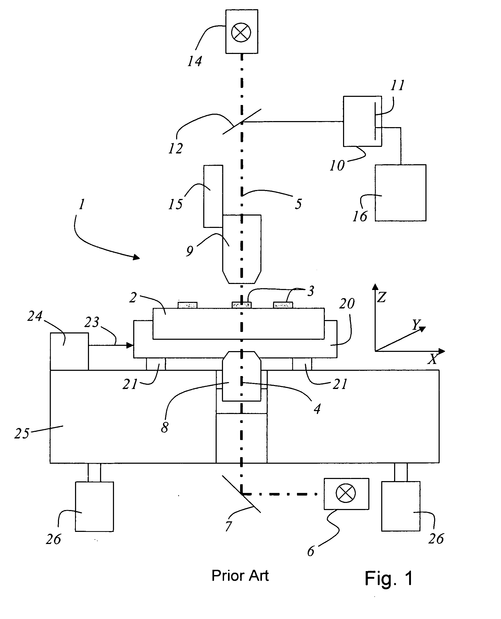
[0026]A coordinate measuring device of the type shown in FIG. 1 has already been described in detail in prior art and is used for implementing the inventive method. The coordinate measuring device 1 includes a measurement table 20 movable in the X-coordinate direction and in the Y-coordinate direction. The measurement table 20 carries a substrate or a mask for the semiconductor production. Several structures 3 are applied to a surface of the substrate 2. The measurement table itself is supported by air bearings 21 which, in turn, are supported by a block 25. The air bearings described herein represent one possible embodiment and are not to be considered as limiting the invention. The block 25 may be made of a granite block. Someone skilled in the art will understand that the block 25 may consist of any material suitable for forming a plane 25a in which the measurement table 20 moves and / or is moved. At least one incident light illumination means 14 and / or one transmitted light illum...


PUM


Abstract

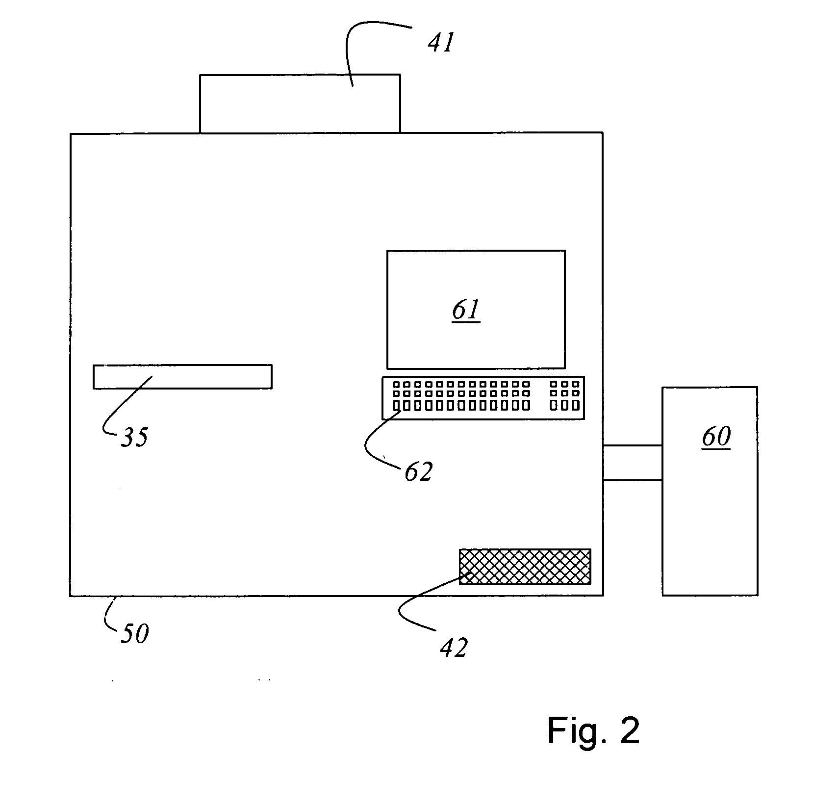
A system for determining positions of structures on a substrate is disclosed. The system includes a plurality of stations enclosed by a housing. At least one of the stations inside the housing is designed to be movable. The housing is provided with a filter fan unit generating an air flow in the housing. Air-directing elements are provided in the housing so that an invariable flow may be achieved irrespective of the at least one movable station.

Description

[0001]This claims the benefits of German Patent Application No. 10 2007 051 391.9, filed on Oct. 25, 2007, and hereby incorporated by reference herein.[0002]The present invention relates to a system for determining positions of structures on a substrate.BACKGROUND OF THE INVENTION[0003]A coordinate measuring device is well-known from prior art. See, for example, the lecture script “Pattern Placement Metrology for Mask Making” by Dr. Carola Bläsing. The lecture was given on the occasion of the Semicon conference, Education Program, in Geneva on Mar. 31, 1998, and described the coordinate measuring machine in detail. The structure of a coordinate measuring machine as known, for example, from prior art will be explained in more detail in the following description associated with FIG. 1. A method and a measuring device for determining the position of structures on a substrate are known from German published application DE 100 47 211 A1. For details regarding the mentioned position deter...

Claims


Application Information

Patent Timeline
IPC IPC(8): G01B11/14
CPCG03F1/84G01B9/02G01B9/02052
Inventor PIETSCH, KATRINADAM, KLAUS-DIETEREHRENBERG, TILLMANN
Owner VISTEC SEMICON SYST
Learn More