Strap driven field mast

a field mast and drive technology, applied in the direction of towers, collapsible antennas, transportation and packaging, etc., can solve the problems of open winch design, prone to accelerated wear-out, and deficient prior art field mast assemblies in a number of ways

Active Publication Date: 2009-04-30
WILL BURT THE
View PDF12 Cites 27 Cited by
  • Summary
  • Abstract
  • Description
  • Claims
  • Application Information

AI Technical Summary

Problems solved by technology

However, the prior art field mast assemblies are deficient in a number of ways.
First, it is a typical and recurring problem that in the process of removing or collapsing the prior art field masts, the individual mast sections will bind and prevent the mast assembly from being placed into its fully collapsed state.
The binding of the mast sections can occur from a variety of reasons, for example, debris trapped between the telescopic mast sections, high wind loads that create a bending moment in the mast sections, or simply lack of proper maintenance and or lubrication of the mast assembly.
Particularly in sandy or dry dusty regions, an open design winch assembly is prone to accelerated wear-out.
This is due to debris or other aggregate materials accumulating on various internal operating components of the winch assembly, such as the bearings, drums, gears, ratchet assemblies, etc.
Moreover, open winch designs create pinch hazards for the operators.
Furthermore, the prior art masts often include a winch assembly that is not easily detached from the mast assembly.
In these cases, a fixed or permanent winch increases the transport weight and creates a bulky protrusion that inhibits the portability and efficient storage of the mast assembly.
In these cases, either valuable time is lost in a system with excessive reduction or increased fatigue is experienced in a system with inadequate speed reduction.

Method used


Image

  • Strap driven field mast
  • Strap driven field mast
  • Strap driven field mast

Examples


Embodiment Construction

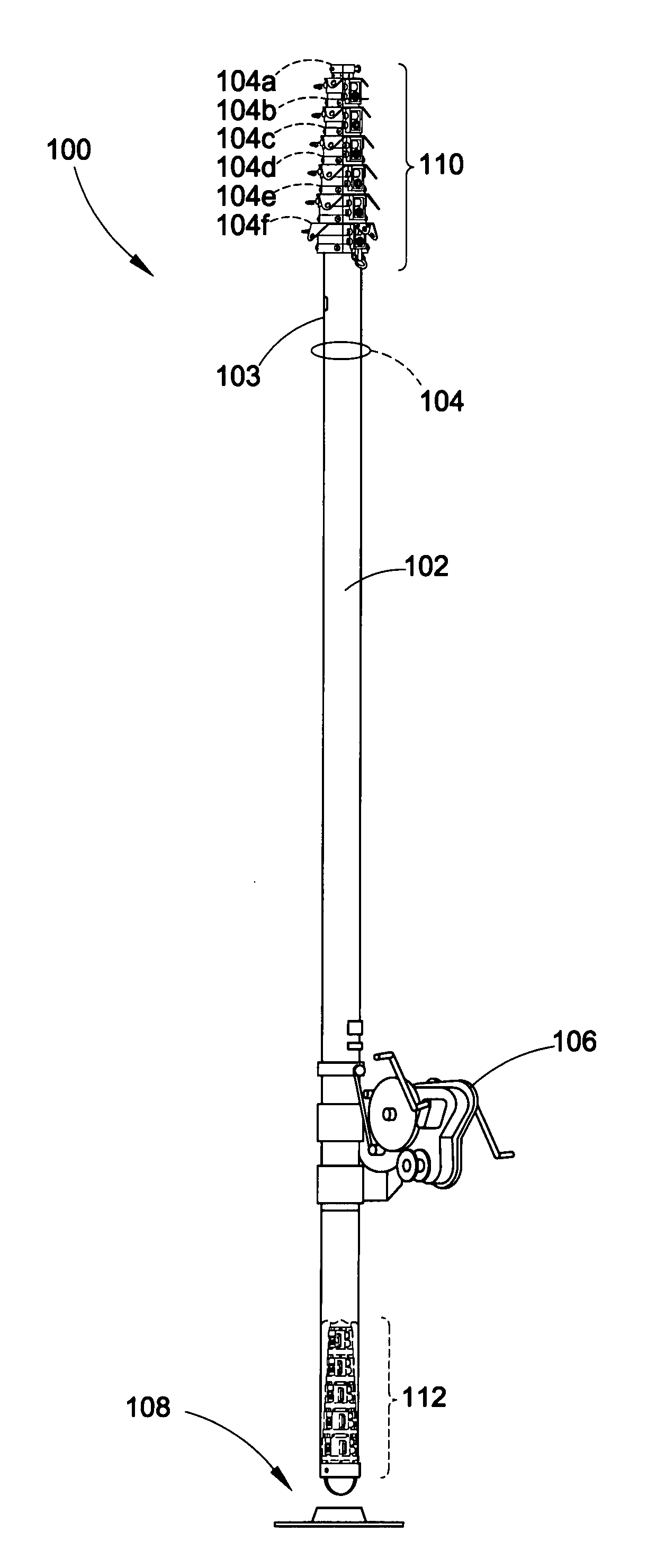
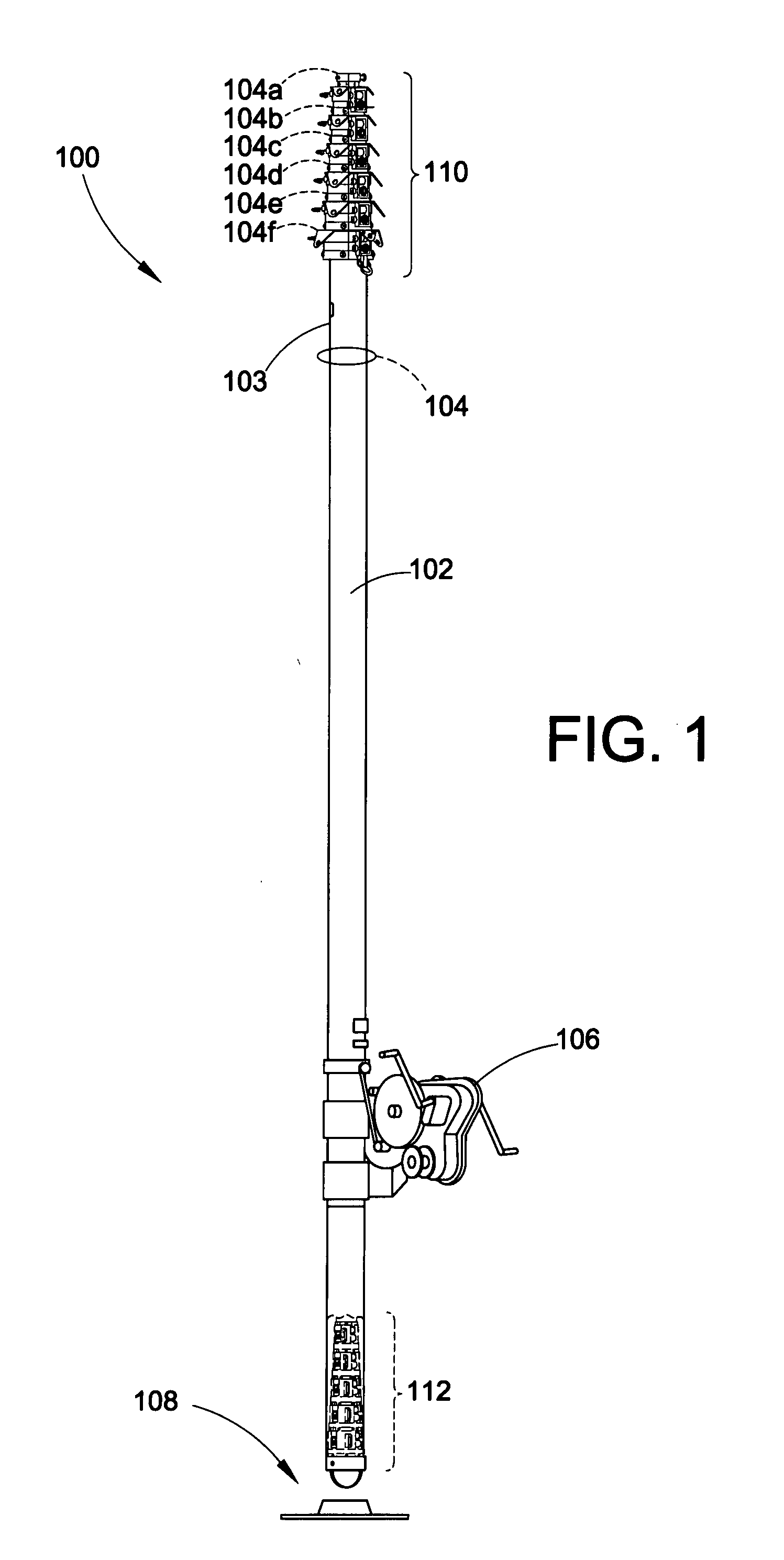
[0027]With reference to FIG. 1, a first embodiment of a telescopic field mast 100 is shown. Generally, the field mast 100 includes an outer body 102, a plurality of nested mast sections 104, a winch assembly 106 and a base 108. The plurality of mast sections 104 may include any number of sections necessary to achieve the height required for a given application. In the present embodiment, a field mast 100 is shown having a total of six (6) mast sections 104a-104f (not including the outer body 102). The first or inner most mast section 104a is typically adapted to carry a particular pay load or associated device (e.g., an antenna, a satellite dish, a vision system, a guidance or positioning system, etc).

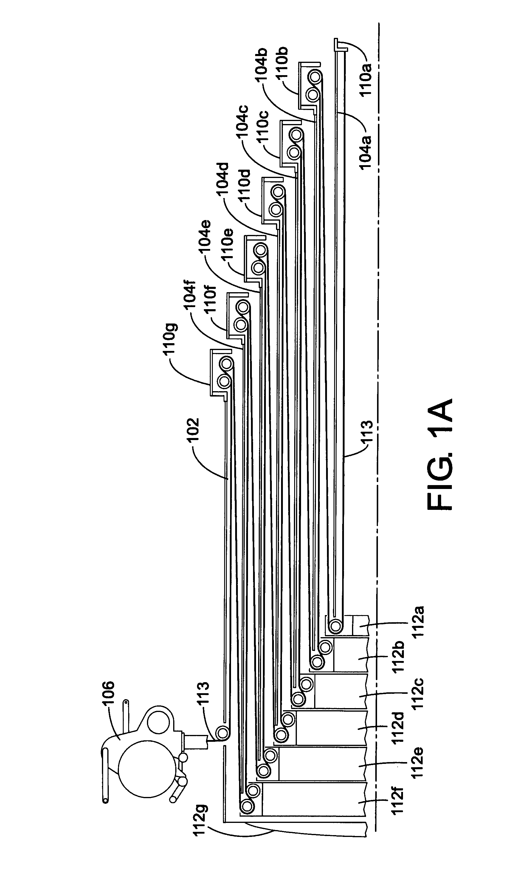
[0028]With reference to FIGS. 1 and 1A, the inner most or first mast section 104a is nested within the second mast section 104b. Similarly, the second mast section 104b is nested within the third mast section 104c which in turn is nested within the fourth mast section 104d and so on. L...


PUM


Abstract

A portable telescopic mast assembly with positive retraction for raising and lowering an associated device includes an outer body and a plurality of mast sections slideably engaged with the outer body. A lifting cable is disposed between the plurality of mast sections. The lifting cable operatively connects the plurality of mast sections so as to urge one or more of the mast sections towards an extended position. The lifting cable includes a first end and a second end, the first end being secured to an inner most mast section of the plurality of mast sections. A retraction cable is disposed at least partially inside the outer body. The retraction cable includes a first end and a second end, the first end being secured to the inner most mast section. A winch is secured to the outer body. The winch includes a first output and a second output, the second end of the lifting cable operatively connected to the first output and the second end of the retraction cable operatively connected to the second output.

Description

BACKGROUND[0001]The present exemplary embodiment relates to extendable masts. It finds particular application in conjunction with portable masts that are intended to be rapidly deployed and or removed while in the field, and will be described with particular reference thereto. However, it is to be appreciated that the present exemplary embodiment is also amenable to other like applications.[0002]Various field mast designs are known in the art. Generally, a field mast is a transportable rapidly deployable support column having a height adjust system for raising or lowering an associated device. The associated device can include a communication, audio / video, and or lighting system or any other device whose function or performance is dependent on height or line of sight operation. Typical applications of such masts include both military and civilian settings where a mast must be erected quickly, quietly and or manually.[0003]However, the prior art field mast assemblies are deficient in...

Claims


Application Information

Patent Timeline
Patent Type & Authority Applications(United States)
IPC IPC(8): E04H12/18
CPCE04H12/182
Inventor KARDOHELY, MICHAEL JAMES
Owner WILL BURT THE
Why Eureka
Try Eureka