
Hybrid mesh belt

a technology of mesh belts and belt edges, applied in the direction of conveyors, driving chains, chain elements, etc., can solve the problems of belt edges being damaged, long belts also suffering from tracking problems, and belt edges may be damaged

Active Publication Date: 2009-04-30
HABASIT AG
View PDF9 Cites 16 Cited by
  • Summary
  • Abstract
  • Description
  • Claims
  • Application Information

AI Technical Summary

Benefits of technology

[0007]The belt of the present invention does not have to be placed under high tension because the sprockets provide positive drive without slippage. The sprockets also provide tracking for the belt. Commonly one sprocket per shaft is fixed, and the other sprockets on the same shaft remain loose in order to allow them to follow the belt when it expands or retracts under varying temperatures and load conditions. In other cases where the mesh fabric is unstable, it may be of advantage to fix both sprockets on the shaft, thus keeping the mesh belt transversally straightened.

Problems solved by technology

One significant problem in the application of such belts is the tracking on the driving and idling drums.
This problem is particularly relevant in the case of short belts, but long belts also suffer from tracking problems.
As a result of these problems, the belt edges may be damaged and may require process interruptions and expensive maintenance work.
Since mesh fabrics are geometrically not totally homogeneous over the width of the belt, equal tensioning over the full belt width can be difficult to achieve.

Method used


Image

  • Hybrid mesh belt
  • Hybrid mesh belt
  • Hybrid mesh belt

Examples


Embodiment Construction

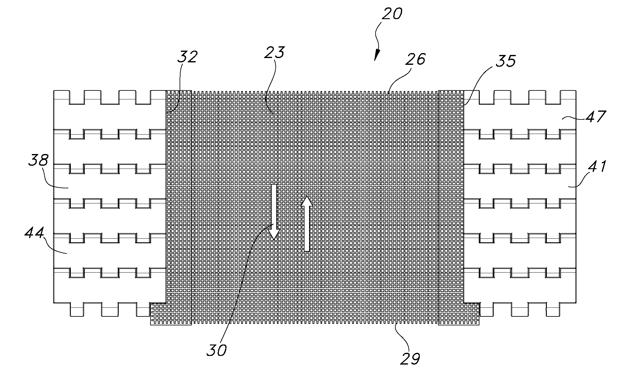
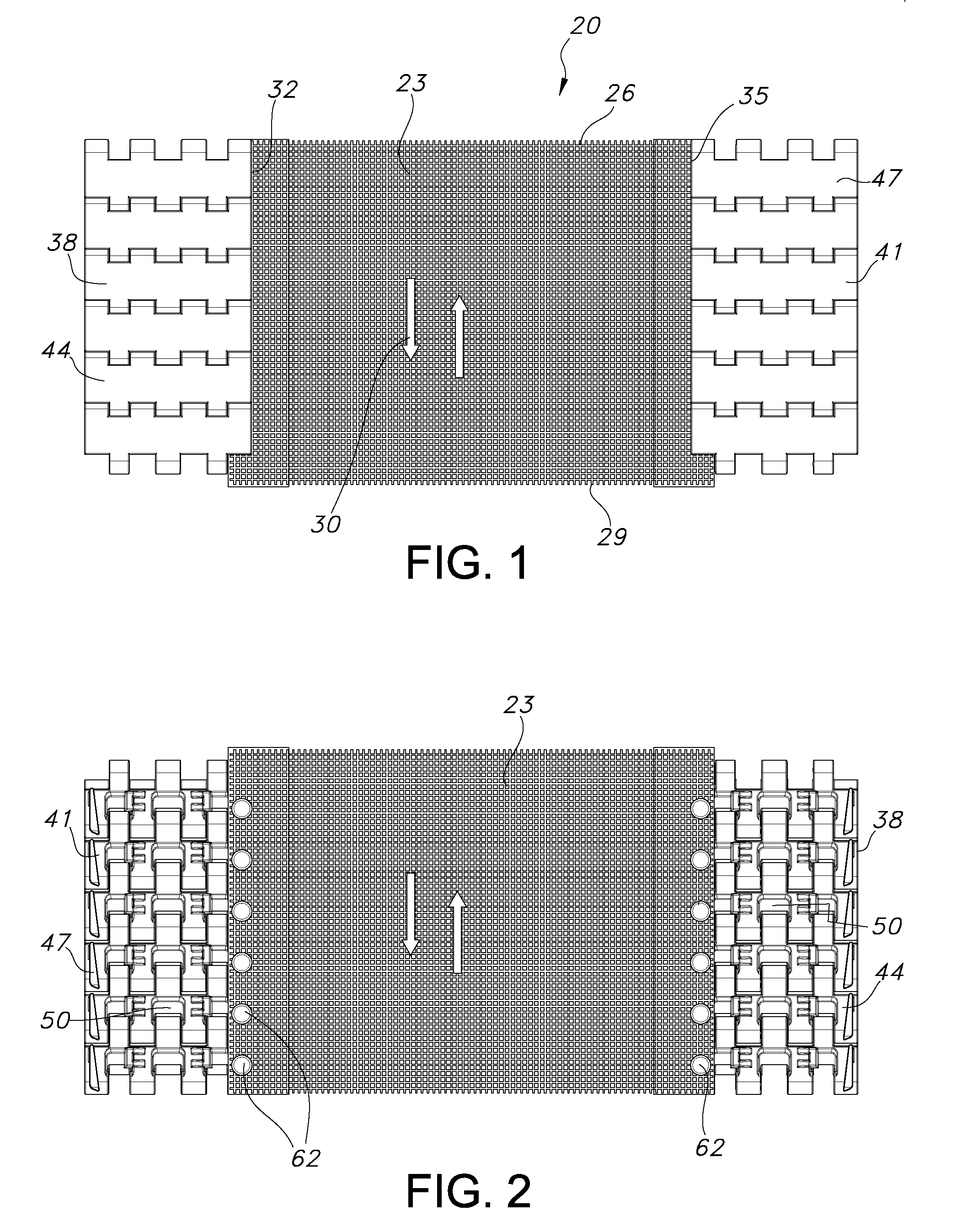
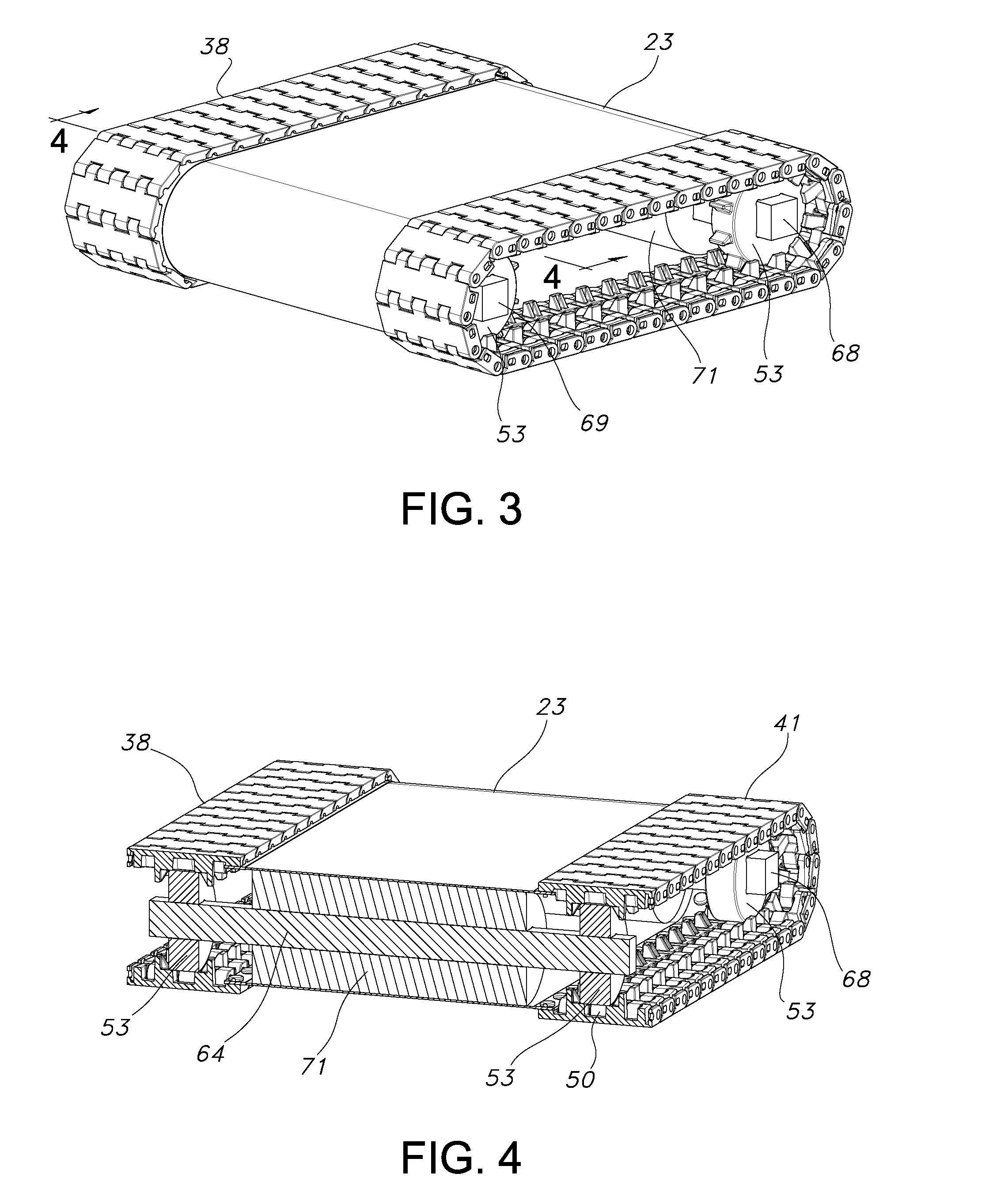
[0027]Referring to FIGS. 1-8 generally and initially to FIG. 1, a hybrid mesh belt 20 according to the present invention is formed with a mesh portion 23. The mesh portion 23 may be formed from woven plastic fibers as will be evident to those of ordinary skill in the art based on this disclosure. The mesh construction is useful for drainage during the wet transport of items such as vegetables. The specific resins used to form the fiber strands, the diameter and weight of the fiber strands, and the weave pattern forming the mesh may be varied depending on many factors. The mesh portion 23 has a leading edge 26 and a trailing edge 29 with respect to a direction of belt travel indicated by arrows 30. The mesh portion 23 is attached such that it forms side edges 32 and 35 disposed on the left and right sides with respect to the orientation of FIG. 1. A pair of chains 38, 41 border the side edges 32 and 35. The chains 38, 41 are plastic modular chains with individual chain modules 44, 47...


PUM


Abstract

A hybrid mesh belt having a mesh portion with side edges attached to modular plastic chains. The chains are provided with cavities on the bottom side. The cavities are suitable for engaging with driving sprockets that engage with the chains.

Description

FIELD OF THE INVENTION[0001]This invention relates generally to conveying belts, and specifically to mesh belts.BACKGROUND OF THE INVENTION[0002]Mesh belts made from woven plastic fibers are widely used for wet transport in the vegetable industry and particularly for salads. The mesh belts are typically provided with sealed belt edges. Coated drums are usually used to drive these belts. One significant problem in the application of such belts is the tracking on the driving and idling drums. This problem is particularly relevant in the case of short belts, but long belts also suffer from tracking problems. As a result of these problems, the belt edges may be damaged and may require process interruptions and expensive maintenance work. Also, belts with these type of drives need to be longitudinally tensioned to allow driving by drums. Since mesh fabrics are geometrically not totally homogeneous over the width of the belt, equal tensioning over the full belt width can be difficult to a...

Claims


Application Information

Patent Timeline
Patent Type & Authority Applications(United States)
IPC IPC(8): F16G13/07F16H7/02
CPCB65G17/02
Inventor DELAIR, JEFFREY E.SZYMBORSKI, JOSEPH G.
Owner HABASIT AG
Learn More