
Steering Mechanism for a Push and Pull Vehicle

a push and pull vehicle and steering mechanism technology, applied in the direction of steering devices, cycle equipment, cycles, etc., can solve the problems of difficult to make swing action and turning action exist independently, and the backlash will not give the rider as solid feeling, and achieve the effect of fast reaction

Inactive Publication Date: 2009-04-16
LEE ROCKY JENLON
View PDF12 Cites 10 Cited by
  • Summary
  • Abstract
  • Description
  • Claims
  • Application Information

AI Technical Summary

Benefits of technology

[0006]Present invention solve the problem and provides maintenance free, solid, fast reaction steering feeling as a regular bicycle while be able to active both push and pull actions; a swing device which contains a handlebar, a swing pole, a turning sleeve, swing arms, a Universal joint (refer as U-joint hereafter), a U-joint bearing, and one-way devices to achieve swing and turning both at same time. Using swing arm and a U-joint, it coordinates swing and turning actions and makes both actions possible to exist independently. As a result:1. U-joint is simple, positive driving, no backlash, and maintenance-free, this makes fast reaction turning same as a regular bicycle.2. Swing arm solid pivot supported on frame and separates from steering, it sustains huge torque from body weight, by a slow motion action to run a good distance and make present invention gracious and easy to operate.

Problems solved by technology

The cable some how always has an elastic result, its backlash will not give rider as solid feeling as a regular bicycle on steering especially at almost stop speed, and because cables natural slacking it needs to be checked and adjusted periodically.
There is a difficulty since swing pole changing its angle all the time in swing action and handlebar on said swing pole changes its angle all the time when turning, like a helicopter blade needs to turn and changing angle at same time, so it is difficult to make swing action and turning action be able to exist independently.

Method used


Image

  • Steering Mechanism for a Push and Pull Vehicle
  • Steering Mechanism for a Push and Pull Vehicle
  • Steering Mechanism for a Push and Pull Vehicle

Examples


Embodiment Construction

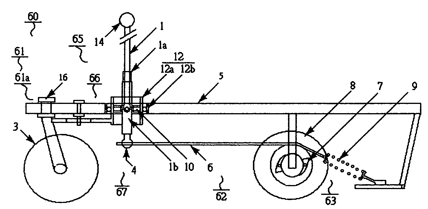
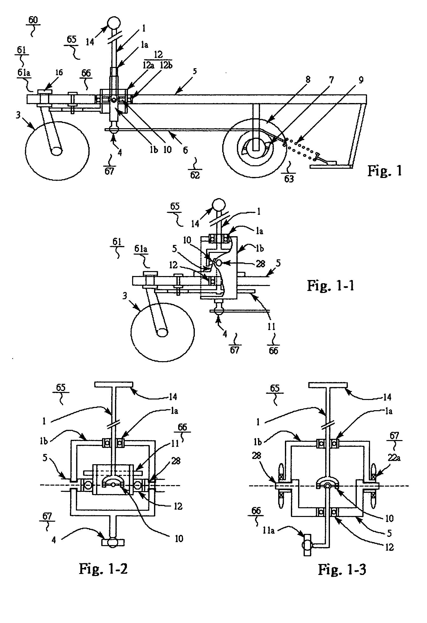
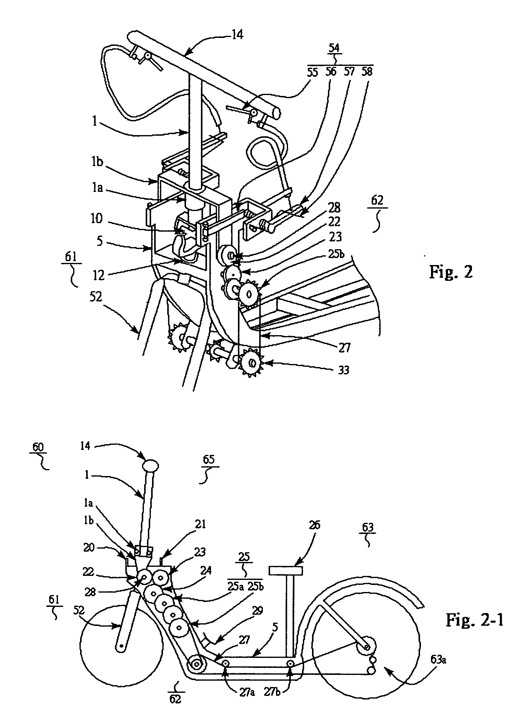
[0039]A swing powered vehicle 60 is a man powered vehicle which using handlebar's pushing forward and (or) pulling back a leverage to drive vehicle moving forward. Present invention makes said vehicle can be steered as a regular bicycle. Refer to FIG. 1, a swing powered vehicle 60 consists of a board or frame 5; a front wheel assembly 61 having a well-known steering mechanism 61a at the front end; a rear wheel assembly 63 containing a one-way device 7 at rear end; a swing device 65 with handlebar at top, has a swing output 67 and contains a pivotal supported on said frame 5, said handlebar 14 also links to said steering mechanism 61a through a steering output 66; and a coupling mechanism 62 which connects said swing output 67 to the rear wheel assemble 63; said swing device 65 bottom side contains a ball joint 4 which pulls a pulling matter 6 to drive a one-way device 7 on rear wheel shaft and reset by a spring 9 at return action.

[0040]Said frame 5 supports all said assemble and pro...


PUM


Abstract

A Steering Mechanism for a Push and Pull Vehicle is to provide a solid turning, fast reaction steering feeling as a regular bicycle steering function, by handlebar turning left or right while still be able to use pulling or pushing action to power a vehicle forward. It contains handlebar at top of swing pole, a turning sleeve on a swing arm to hold swing pole, a frame supported U-joint bearing holds a U-joint which steer vehicle direction, and said swing arm contains a pivot support on vehicle frame and output to drive vehicle forward. So said handlebar is able to swing back and forth on swing arm pivot support to drive vehicle forward and turn left and right on said turning sleeve for steering directions.

Description

CROSS REFERENCE TO RELATED APPLICATION[0001]This application claims the benefit of and priority from U.S. provisional application No. 60 / 979,814 filed on Oct. 13, 2007BACKGROUND OF INVENTION[0002]1. Field of the Invention[0003]Present invention relates to a push-and-pull action to power a vehicle. A pushing or a pulling or a push-pull action refers to a swing action hereafter which uses single pushing, single pulling or both push-pull forces by hand, feet or body weight. Present invention can be applied on handlebar skateboards, pushing scooters, bicycles, scooters, electric bike, and bike-quads. By using a handlebar as leverage, it makes said vehicle moving forward and at same time handlebar steers front wheel(s) to turn vehicle direction by turning left and right as a bicycle's handlebar.[0004]2. Brief Description of the Prior Art[0005]U.S. Pat. Nos. 6,764,089, 7,195,264, USA Rowbike at www.rowbike.com has a row machine on a bicycle, it only applies on single pulling action and us...

Claims


Application Information

Patent Timeline
IPC IPC(8): B62D1/20
CPCB62K3/005B62M1/16B62K21/00
Inventor LEE, ROCKY JENLON
Owner LEE ROCKY JENLON
Learn More