Load-lifting member with bolted joint

a bolted joint and load-lifting technology, applied in the direction of lifting devices, etc., can solve the problems of increased stress and bolt-on clamp arms

Inactive Publication Date: 2009-05-07
CASCADE CORP
View PDF9 Cites 15 Cited by
  • Summary
  • Abstract
  • Description
  • Claims
  • Application Information

AI Technical Summary

Problems solved by technology

However, other types of loading cause increased stresses.
A similar problem exists in the case of bolt-on clamp arms.

Method used


Image

  • Load-lifting member with bolted joint
  • Load-lifting member with bolted joint
  • Load-lifting member with bolted joint

Examples


Embodiment Construction

[0022]In the following detailed description, numerous specific details are set forth in order to provide a thorough understanding of the preferred embodiments. However, those skilled in the art will understand that the present invention may be practiced without these specific details, that the present invention is not limited to the depicted embodiments, and that the present invention may be practiced in a variety of alternate embodiments. In other instances, well known methods, procedures, components, and systems have not been described in detail.

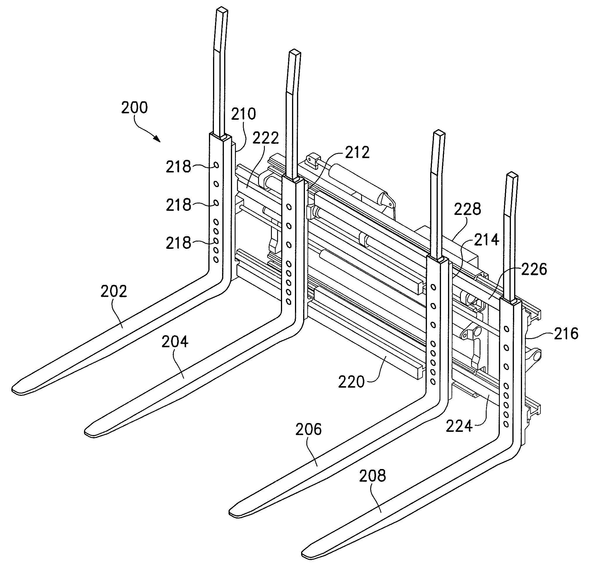
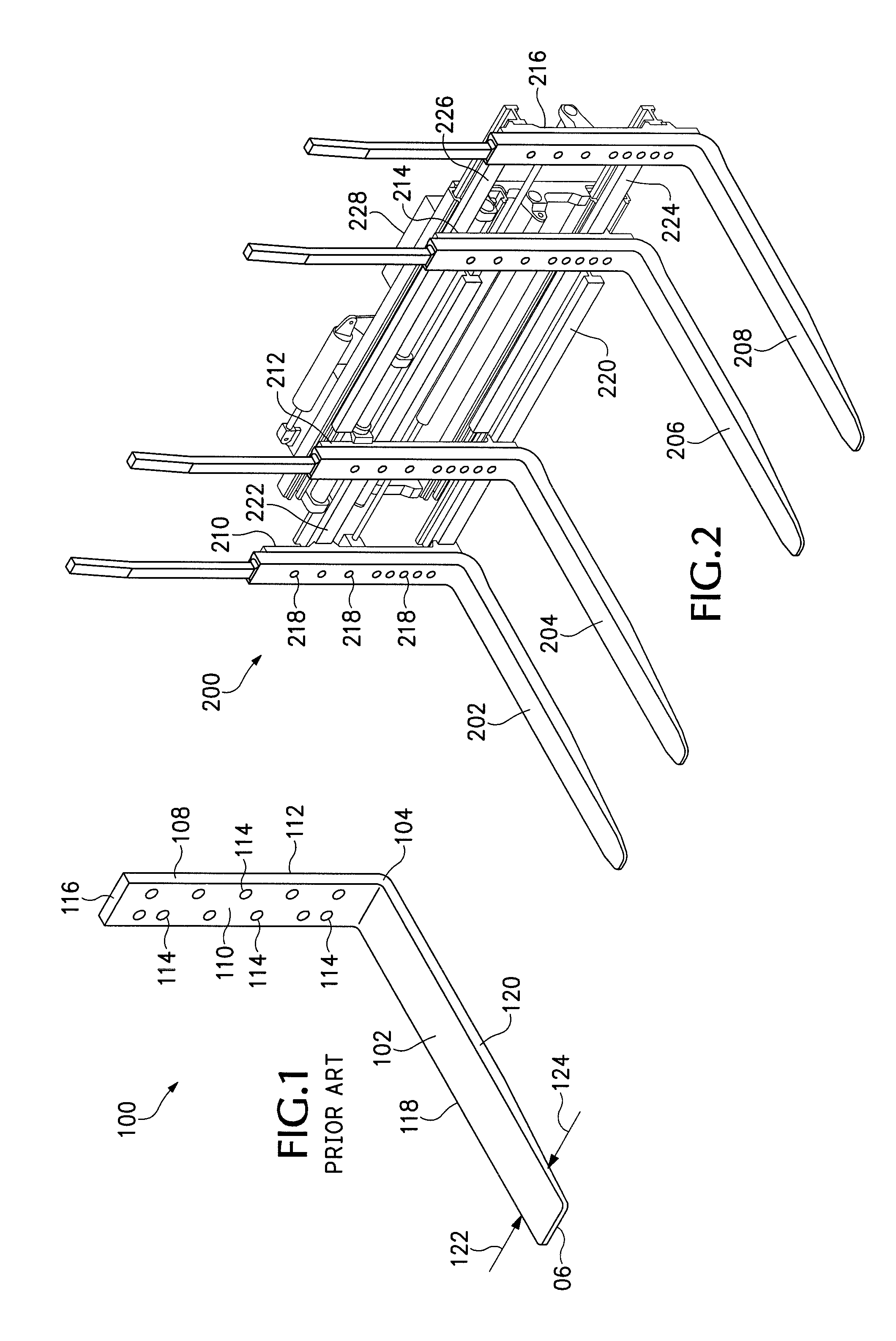
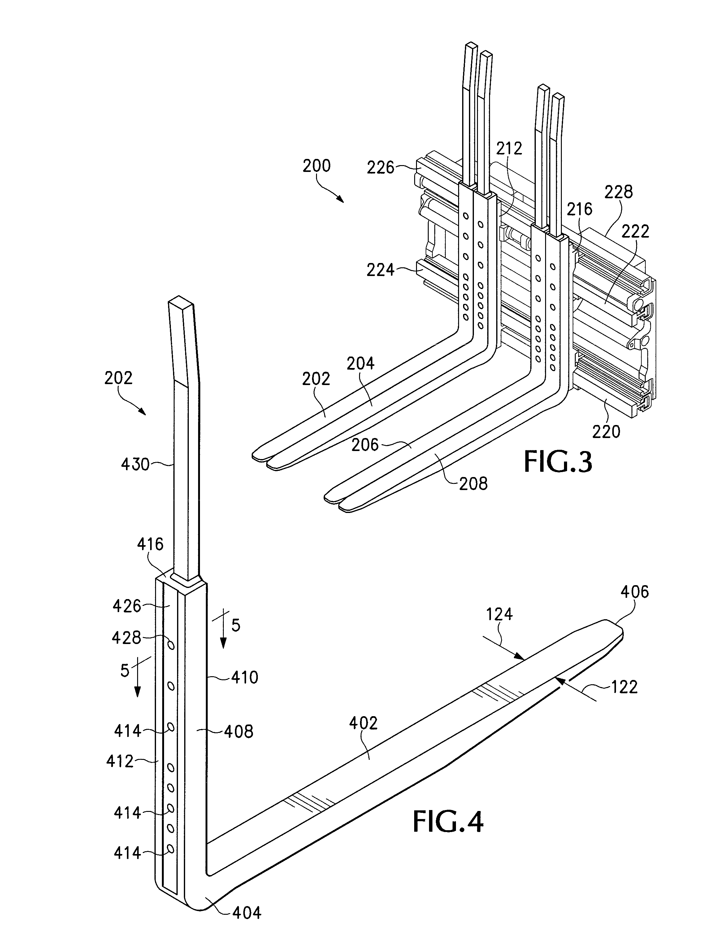
[0023]As an overview, the preferred embodiments generally involve improved bolted joint designs applicable for a joint between a bolt-on type load-lifting fork or clamp arm and a carriage or carrier. Although the present invention may be implemented in a wide variety of configurations involving different types of material handling attachments, the following detailed description discloses the preferred embodiments principally in the context...


PUM


Abstract

Improved bolted joint designs are used for a joint between a bolt-on load-lifting member such as a fork or clamp arm and a carriage or carrier associated with a material handling device. In various embodiments, an elongate rear vertical shank of one or the other of the load-lifting member or the carrier may have a plurality of mounting bolt holes spaced longitudinally along its length, each mounting bolt hole extending from a respective recessed area formed in one or both of the joined surfaces. Each bolt hole has a respective bolt-hole width dimension transverse to the elongate member, and each recessed area has a recess width dimension parallel to and greater than the bolt-hole width dimension.

Description

BACKGROUND OF THE INVENTION[0001]This disclosure relates generally to bolted joints for use with material handling equipment and, more particularly, to improved bolted joint designs applicable for a joint between a bolt-on type load-lifting member, such as a fork or clamp arm, and a carriage or fork carrier.[0002]Material handling equipment used for moving palletized or non-palletized loads from place to place, such as, for example, in a warehouse, typically includes forklift trucks or other types of vehicles equipped with material handling attachments having load-lifting members such as forks or clamp arms. For example, on a typical forklift truck, the load-lifting forks are attached to a carriage (or fork carrier) which is in turn movably attached to a mast. The carriage travels vertically along the mast for raising and lowering the forks. The carriage typically comprises flat metal surfaces upon which the forks are mounted using hooks, pins (or shafts), or bolts.[0003]Various dif...

Claims


Application Information

Patent Timeline
Patent Type & Authority Applications(United States)
IPC IPC(8): B66F9/14
CPCB66F9/12B66F9/183B66F9/14
Inventor WHITE, BRIAN SINCLAIRJORDAN, DEAN CLARKKEAGBINE, ANTHONY PAUL
Owner CASCADE CORP
Why Eureka
Try Eureka