Magnetically Mounted Motivation Device With Integrated Indicator

a magnetically mounted, motivation device technology, applied in the field of electronic devices, can solve the problem that conventional electronic devices are not typically in proximity to dieters

Inactive Publication Date: 2009-05-14
CD3
View PDF14 Cites 2 Cited by
  • Summary
  • Abstract
  • Description
  • Claims
  • Application Information

AI Technical Summary

Benefits of technology

[0007]Disclosed is a magnetically mounted motivation device with an integrated indicator. A generally circular planar case includes a partially flexible upper surface and a lower surface that includes an acoustically transparent area. An audio storage element mounted within the generally circular planar case stores multiple spoken motivational messages. An audio output device coupled to the audio storage element is mounted within the generally circular planar case overlying the acoustically transparent area. If a switch mounted within the generally circular planar case and underlying the partially flexible upper surface is activated, the audio output device outputs one or more of the spoken motivational messages. A magnetic base mounted to an outer portion of the lower surface of the generally circular planar case surrounds the acoustically transparent area such that audio output is not impeded. A rotatable bezel mounted to the generally circular planar case includes multiple indicia that are indicated by a rotational position of the rotatable bezel.

Problems solved by technology

Broadcasting a user's current weight can counteract the motivational effects of a weight loss system, since the user may feel embarrassed or intimidated by the numerical value of his or her weight.
However, conventional electronic devices are not typically in proximity to a dieter at moments when the user may become tempted to stray from their diet plan (e.g., in a kitchen).

Method used


Image

  • Magnetically Mounted Motivation Device With Integrated Indicator
  • Magnetically Mounted Motivation Device With Integrated Indicator
  • Magnetically Mounted Motivation Device With Integrated Indicator

Examples


Embodiment Construction

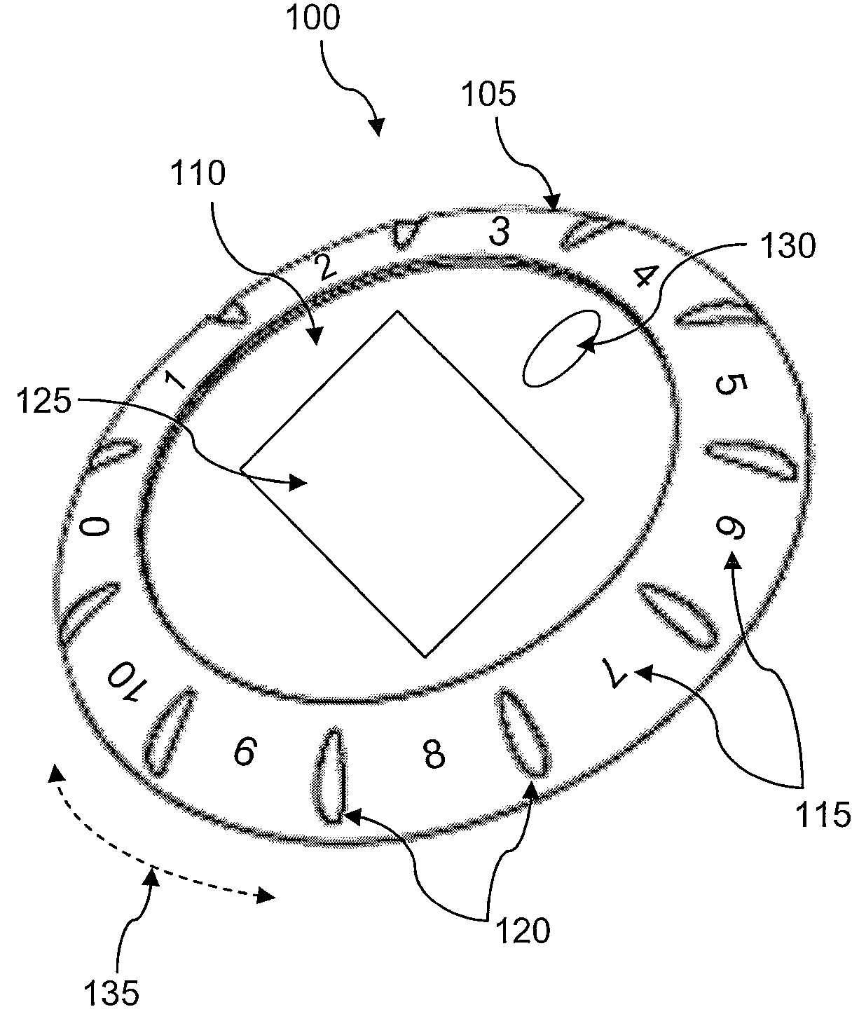
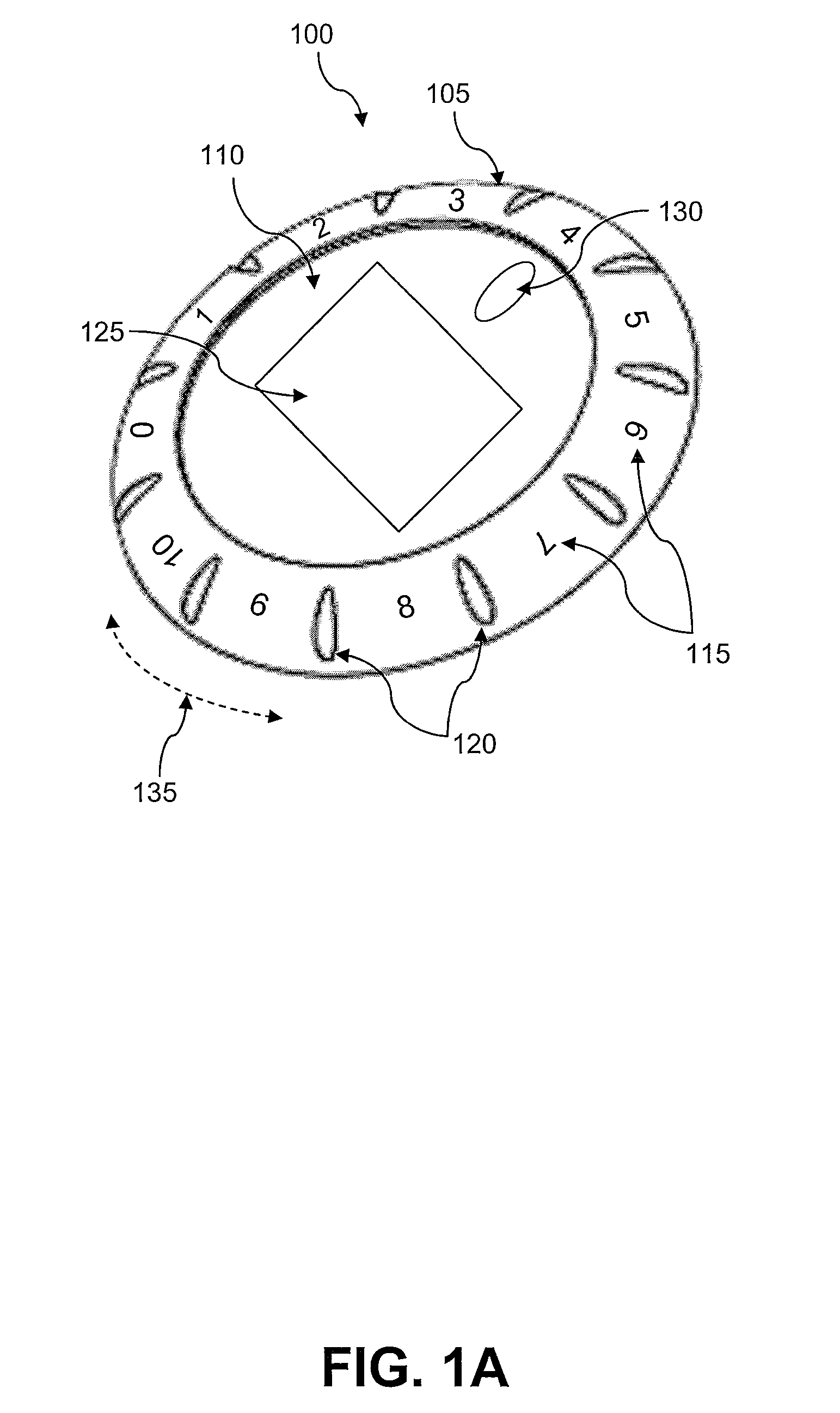
[0013]The present invention provides a magnetically mounted motivation device with an integrated indicator.

[0014]With reference now to FIG. 1A, there is depicted a high level block diagram of a magnetically mounted motivational device with an integrated indicator, as utilized in an embodiment of the present invention. As shown, magnetically mounted motivation device 100 includes an indicator 105 and a partially flexible upper surface, such as front shell 110. Front shell 110 may be a partially flexible rubber dome, partially flexible plastic shell, or the like. As utilized herein, an indicator refers to a rotatable bezel, ring, rim, and / or covering that fits on top of front shell 110 and may move rotationally with respect to front shell 110, as shown by motion line 135. Motion line 135 is provided for illustrative purposes only. A user of magnetically mounted motivation device 100 may selectively press the partially flexible front shell 110 to actuate a push button that performs the...


PUM


Abstract

A magnetically mounted motivation device with an integrated indicator is disclosed. A generally circular planar case includes a partially flexible upper surface and a lower surface that includes an acoustically transparent area. An audio storage element mounted within the generally circular planar case stores multiple spoken motivational messages. An audio output device coupled to the audio storage element is mounted within the generally circular planar case overlying the acoustically transparent area. If a switch mounted within the generally circular planar case and underlying the partially flexible upper surface is activated, the audio output device outputs one or more spoken motivational messages. A magnetic base mounted to an outer portion of the lower surface of the case surrounds the acoustically transparent area such that audio output is not impeded. A rotatable bezel mounted to the case includes multiple indicia that are indicated by a rotational position of the rotatable bezel.

Description

BACKGROUND OF THE INVENTION[0001]1. Technical Field[0002]The present invention relates in general to electronic devices and in particular to electronic motivational devices. Still more particularly, the present invention relates to an improved magnetically mounted motivation device with an integrated indicator.[0003]2. Description of the Related Art[0004]Dieters typically seek to achieve broad goals, such as losing a dress size or simply looking better in their clothes. Rather than continuously tracking the specific numerical value of their weight, dieters focus on round numbers (e.g., losing 10 pounds). A dieter may not wish their current weight to be displayed or widely announced to family members, friends, or passers by. Broadcasting a user's current weight can counteract the motivational effects of a weight loss system, since the user may feel embarrassed or intimidated by the numerical value of his or her weight.[0005]Electronic devices utilize speech synthesis devices to emula...

Claims


Application Information

Patent Timeline
Patent Type & Authority Applications(United States)
IPC IPC(8): G09B5/04
CPCG09B19/00G09B5/04
Inventor HUNT, RONALD EUGENEWHITEHEAD, VERLON EUGENEBARRETT, TOD ALAN
Owner CD3
Why Eureka
Try Eureka