
Pavement marker

Active Publication Date: 2005-02-08
ENNIS PAINT
View PDF7 Cites 5 Cited by
  • Summary
  • Abstract
  • Description
  • Claims
  • Application Information

AI Technical Summary

Benefits of technology

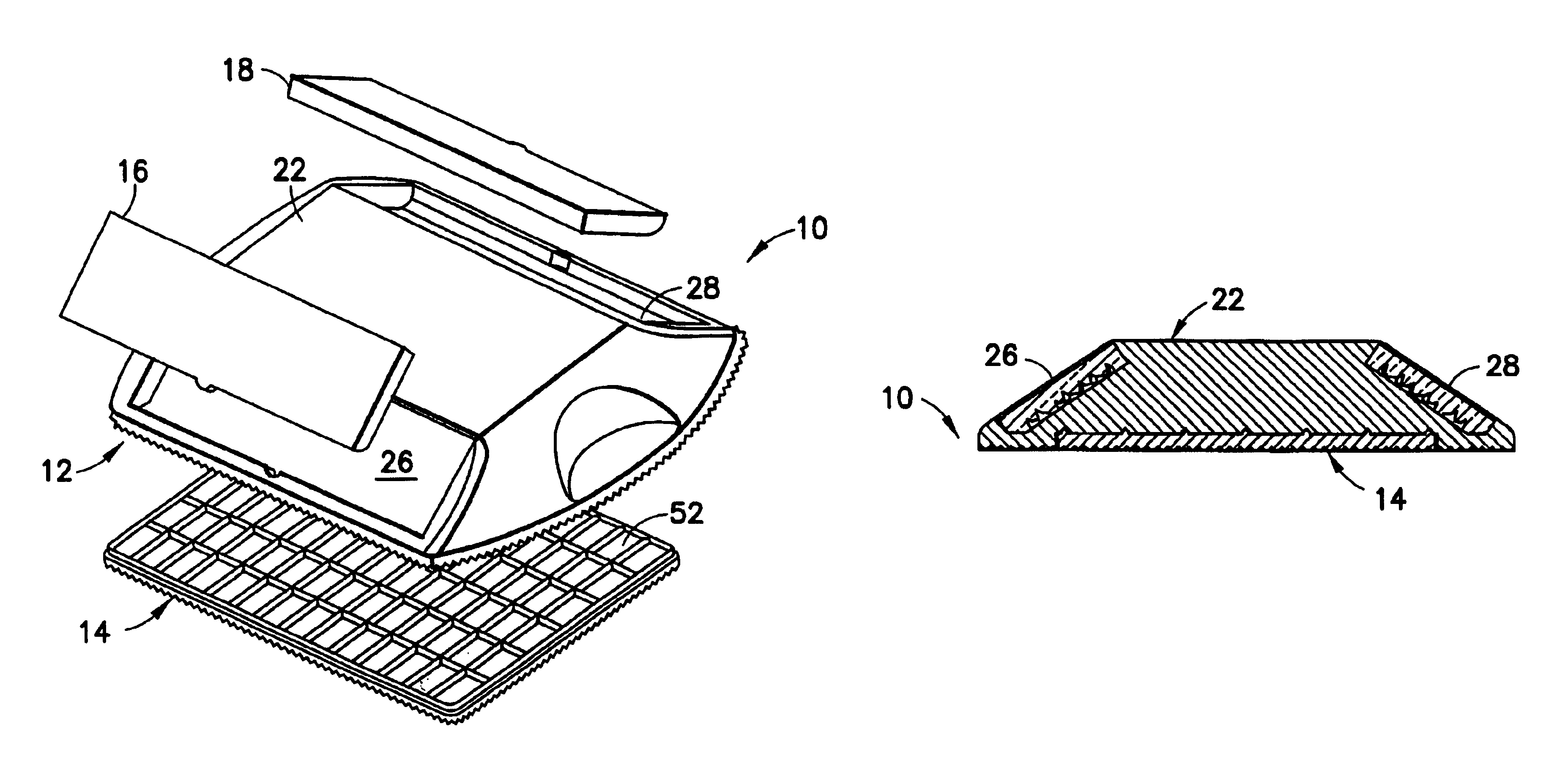
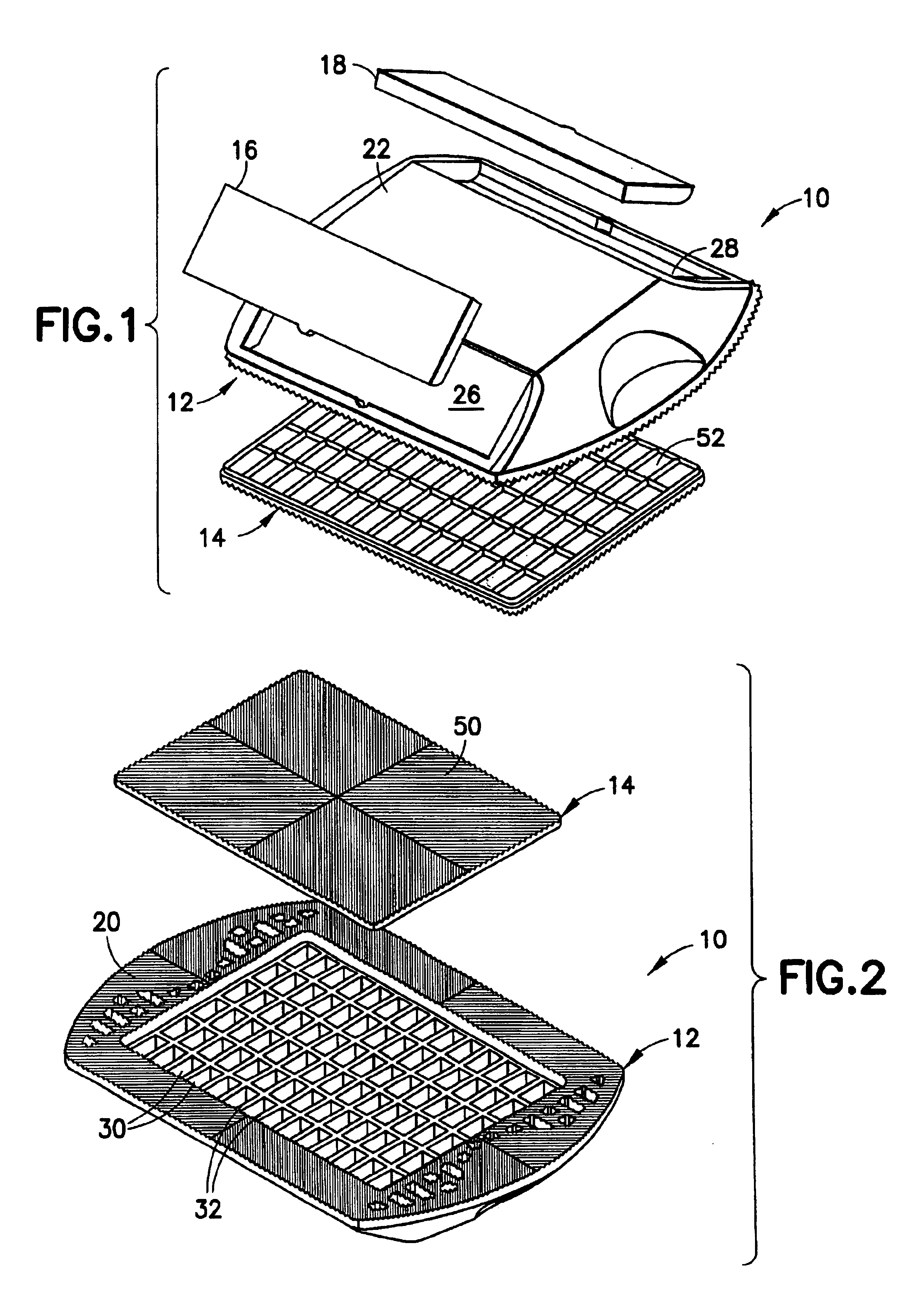
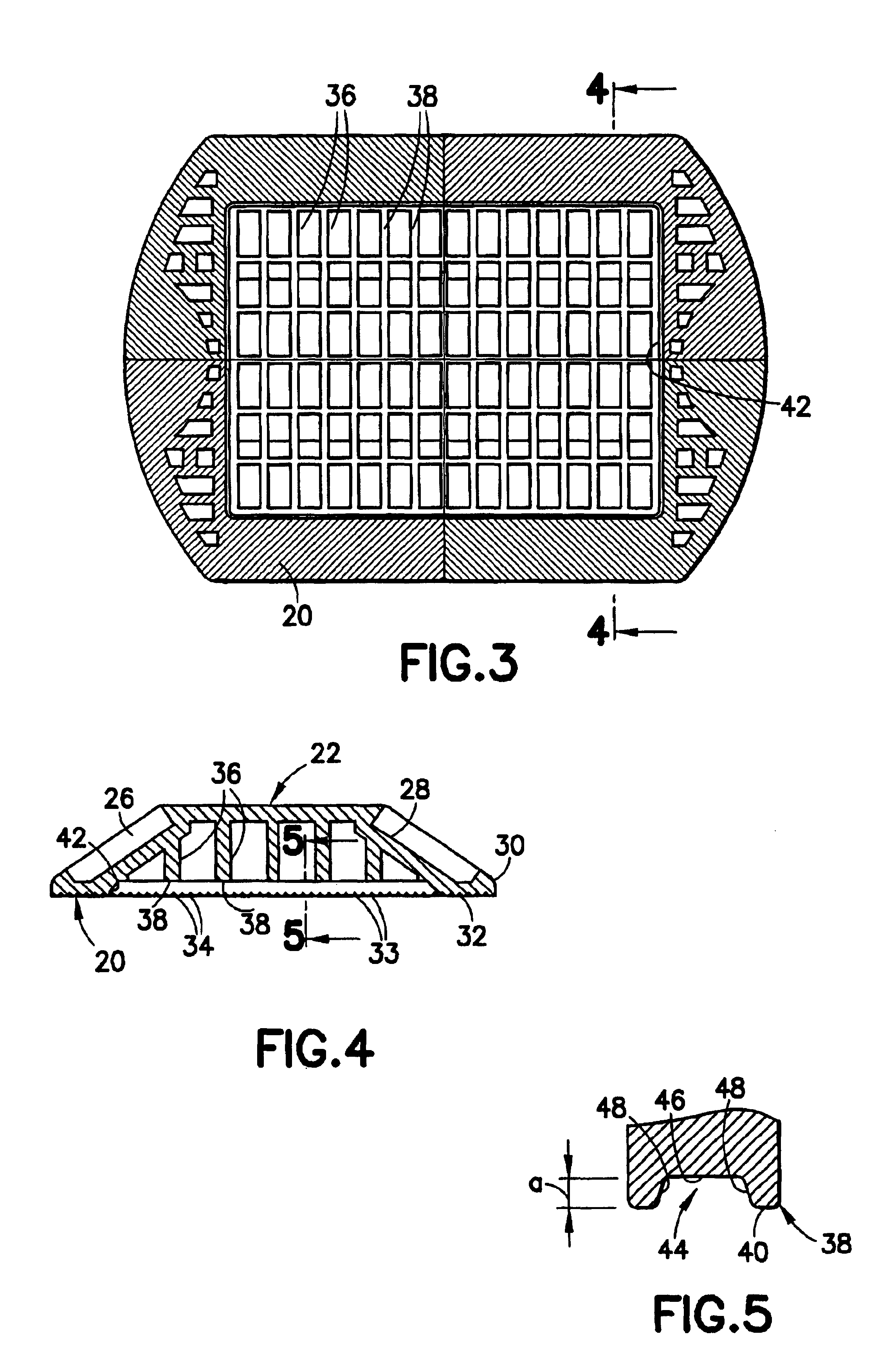
The subject invention relates to a pavement marker having at least first and second components that are ultrasonically welded to one another. The first component is formed with at least one weld channelizing groove and the second component is formed with at least one energy directing rib that nests with the groove when the first and second components are assembled properly. The first and second components are welded ultrasonically to one another at the interface of the energy directing rib and the weld channelizing groove. As a result, an integral matrix of weldment exists at the interfitting surfaces defined by the rib and the mating side and base surfaces of the groove. Accordingly, a large, predictable and more effective attachment area is defined for the ultrasonic weldment with a corresponding increased bond potential and a stronger bond.
The energy directing rib on the second component may initially be pointed to form a well defined region for receiving the ultrasonic energy that will achieve the welded connection between the first and second components. A groove on the first component may define a rectangular cross-section. The cross-sectional areas of the rib and the groove may approximately equal one another so that the material of the rib will substantially fill the groove after ultrasonic welding for maximizing bonding potential.
The method step of forming the energy directing rib may comprise forming the rib with a pointed edge, and the method step of forming the groove may comprise forming a groove of substantially rectangular cross-section. The formation of the rib and the groove preferably are carried out so that the groove defines a cross-sectional area at least equal to a cross-sectional area defined by the rib. Thus, the ultrasonic welding step will cause the rib to melt and substantially fill the groove, with surface-to-surface bonding between the rib and the inwardly facing surfaces of the groove. However, the ultrasonic welding step will not create an excess of weldment that will impede proper mounting of the first and second components to one another. The ultrasonic welding may be carried out to achieve a hermetic seal.

Problems solved by technology

Injection molded plastic products that are thick require a long time to cure and create the potential for sink marks or other dimensional irregularities.
Coring holes that extend in a side-to-side or front-to-rear direction on the base of a pavement marker could affect the strength of the base and could lead to failure in response to impact by vehicular tires.
Coring holes that extend into the bottom surface of a pavement marker necessarily reduce the surface area, and hence can adversely affect the retention of the pavement marker on the pavement.
However, a substantial portion of the hardened pool of plastic will contribute little or nothing to the secure attachment of the panel or cover to the base.
Consequently, the energy expended and the time allotted for ultrasonic welding is not always commensurate with the benefit achieved.
Additionally, the strength of some ultrasonic welds may not be adequate to withstand stresses imposed by vehicular tires.

Method used


Image

  • Pavement marker
  • Pavement marker
  • Pavement marker

Examples


second embodiment

While the invention has been described with respect to certain preferred embodiments, it is apparent that various changes can be made without departing from the scope of the invention as defined by the appended claims. For example, the interengagement of grooves with energy directors can be applied to the lens recesses and lenses in either the first or Additionally, other patterns of grooves and energy directors and other configurations of grooves and energy directors can be provided.


PUM

PropertyMeasurementUnit
Energyaaaaaaaaaa
Fluorescenceaaaaaaaaaa
Optical propertiesaaaaaaaaaa

Abstract

A pavement marker has a base having at least one opening formed therein. A groove is formed in the base substantially adjacent the opening. The pavement marker further includes a cover for covering the opening in the base. The cover is formed with at least one energy directing rib configured for nesting with the groove in the base. The cover is ultrasonically welded to the base so that the energy directing rib melts and integrally fuses to portions of the base adjacent the groove.

Description

BACKGROUND OF THE INVENTION1. Field of the InventionThe invention relates to a pavement marker that reflects and / or transmits light for identifying selected regions of a driving surface.2. Description of the Related ArtPavement markers are secured on or in a pavement surface to help direct drivers along preferred travel lanes. A typical pavement marker includes a plurality of separate components selected to perform specified functions. For example, a typical pavement marker may include a base and at least one light transmissive or retroreflective panel mounted to the base to produce optical signals that will be visually apparent to a driver approaching the pavement marker. The base of a surface-mounted pavement marker typically may be molded from a thermoplastic material and may include a bottom surface configured for affixation on the surface of the pavement. The base may further include a top area configured for receiving the light transmissive and / or retroreflective panel.Injecti...

Claims


Application Information

Patent Timeline
IPC IPC(8): B29C65/00E01F9/04B29C65/08
CPCB29C66/322B29C66/5326E01F9/042B29C65/08B29C66/30223B29C65/00B29C66/124B29C66/234B29C66/71E01F9/512B29K2069/00B29C45/00
Inventor SNAGEL, PAULLANGLANDS, DAVIDSARDESAI, SWANAND
Owner ENNIS PAINT
Learn More