High Efficiency Water Pick Cleaning Apparatus and Showerhead

a cleaning apparatus and high-efficiency technology, applied in the field of high-efficiency water pick cleaning apparatus and showerhead, can solve the problems of wasting energy, splatter and residue around the bathroom mirror, and the constant stream of water for dislodging food and plaque is not as effective as its pulsating predecessor,

Inactive Publication Date: 2009-05-14
REICH BONNIE E +1
View PDF10 Cites 126 Cited by
  • Summary
  • Abstract
  • Description
  • Claims
  • Application Information

AI Technical Summary

Benefits of technology

[0023]The inventive pulsating water pick is used in combination with a pulsating showerhead supplied with pressurized water. The showerhead includes an outer housing defining an input port and an internal chamber supplied with pressurized water. A rotatable impeller is mounted in the outer housing and has a plurality of radially extending fins mounted on an impeller plate. The impeller plate has partially blocking circumferential segments such that water flow causes said impeller to rotate due to blocked flow about said partially blocking circumferential segments. The impeller is rotatably mounted atop a fixed regulator plate which is fixed in said outer housing. The regulator plate has a plurality of groups of holes. Each group of holes being a plurality of holes and each group circumferentially spaced apart about the regulator plate. The showerhead also includes a control plate beneath the regulator plate. The regulator plate is intermediate the impeller and the control plate. The control plate is rotatably mounted in the outer housing and ...

Problems solved by technology

Traditional water picks are typically used in a bathroom near the sink, and by the end of the cleaning process, leave splatter and residue around the bathroom mirror and sink.
It became obvious that a constant stream of water for dislodging food and plaque was not as effective as its pulsating predecessor.
The major issue with...

Method used


Image

  • High Efficiency Water Pick Cleaning Apparatus and Showerhead
  • High Efficiency Water Pick Cleaning Apparatus and Showerhead
  • High Efficiency Water Pick Cleaning Apparatus and Showerhead

Examples


Embodiment Construction

[0033]The present invention relates to a showerhead with a pulsating water pick attachment. Similar numerals designate similar items throughout the drawings and the specification.

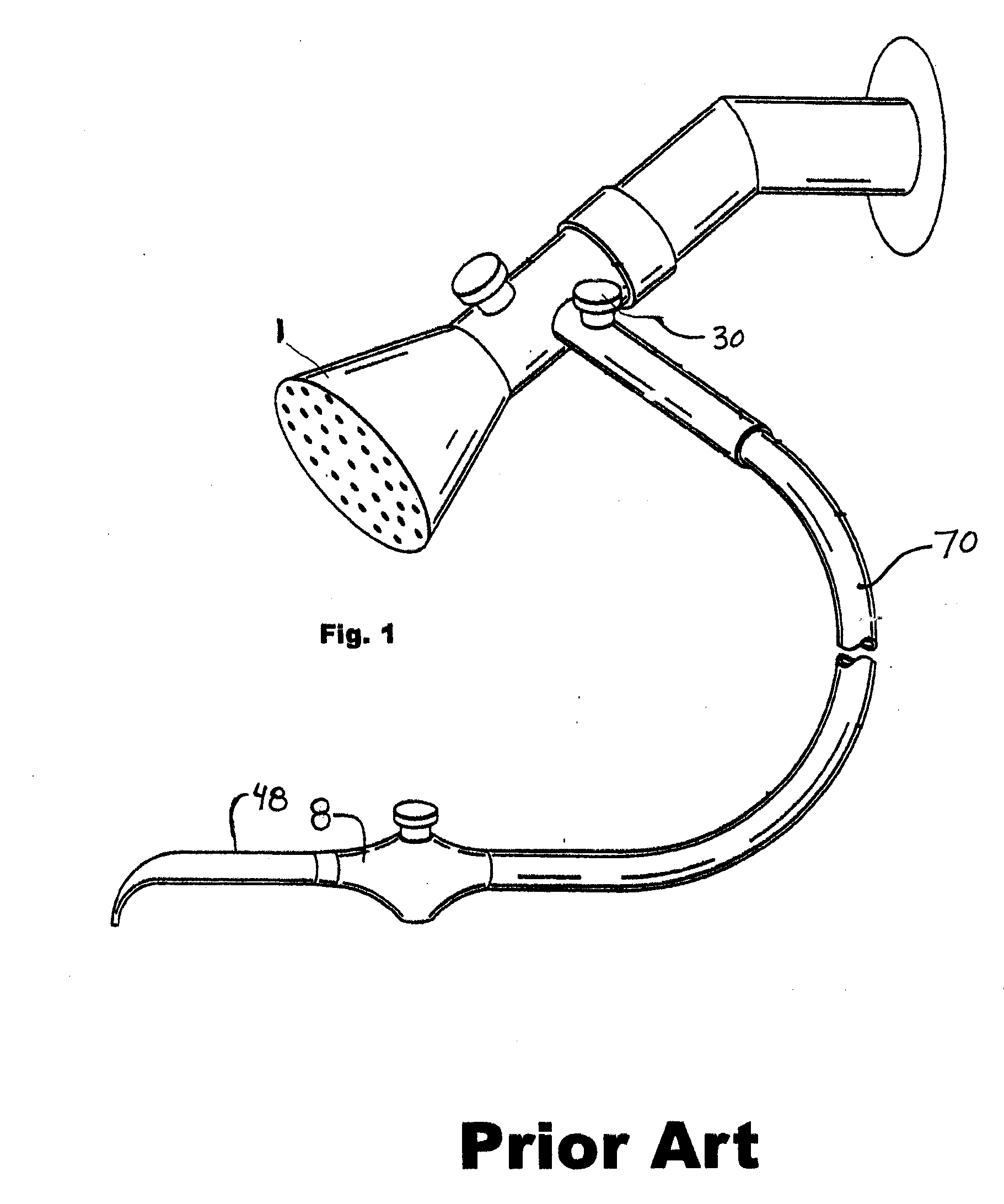
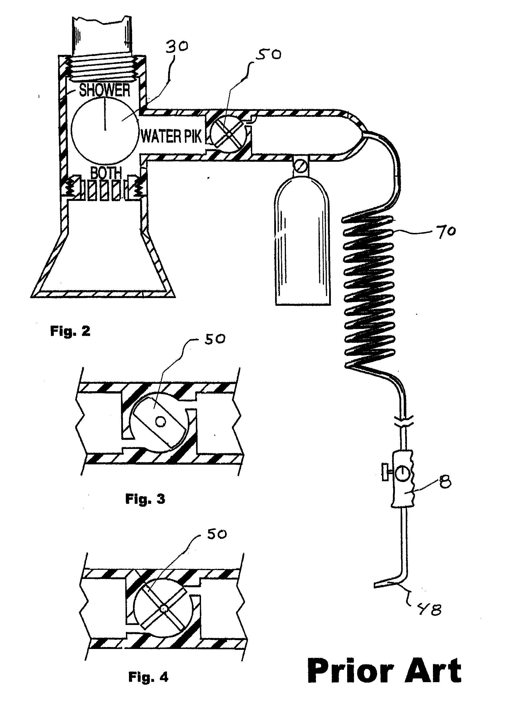
[0034]FIGS. 1-4 diagrammatically illustrate prior art. FIG. 1 diagrammatically illustrates the prior art of U.S. Pat. No. 5,220,914, the disclosure of which is incorporated herein by reference thereto. It contains a showerhead 1 with a diverter valve 30 that allows water to flow into tube 70 to handle 8 and through water pick tip 48. FIG. 2 diagrammatically illustrates the prior art of U.S. Pat. No. 5,484,281. It includes several features from U.S. Pat. No. 5,220,914 and adds an impeller 50 to pulsate the water flowing towards the water pick tip 48. FIGS. 3 and 4 diagrammatically illustrate alternative impeller configurations of the prior art.

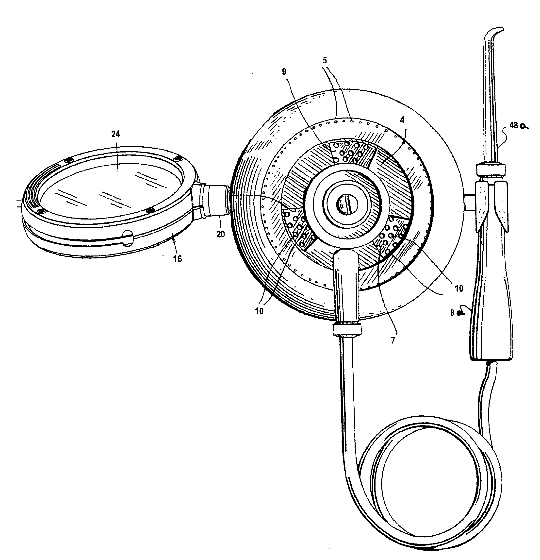
[0035]FIG. 5 diagrammatically illustrates is an exploded diagram of the components inside a typical pulsating showerhead modified in accordance with the principles of ...


PUM


Abstract

The inventive pulsating water pick is used in combination with a pulsating showerhead supplied with pressurized water. The showerhead includes rotatable impeller periodically blocking water flow to a fixed regulator plate having circumferentially spaced apart groups of holes. A rotatable control plate—showerhead ejector face plate therebeneath has at least one opening sized to expose one group of holes. Raised lands limit water flow between adjacent plates and depressed areas lead to peripheral shower holes in a peripheral channel. The control plate rotates and plate openings expose hole groups in one mode, but in another, holes are blocked and water flows to depressed areas and the peripheral shower holes in the peripheral channel. The improved pulsating water pick includes a water passage port formed in the control plate and the showerhead ejector face plate, a coupler thereat leading to a tube, a water pick handle and a pick nozzle.

Description

[0001]This is a regular patent application based upon and claiming the benefit of provisional patent application Ser. No. 61 / 002,146, filed Nov. 8, 2007, the contents of which is incorporated herein by reference thereto.[0002]The present invention relates to a shower head with a pulsating water pick attachment.BACKGROUND[0003]A traditional water pick uses water pumped under pressure and is directed at teeth, gums, and tongue for oral hygiene. Ideally the water flow through the dental water pick should have sufficient pressure and pulsation to dislodge plaque and food particles from the teeth and gums. Water picks also come with a variety of tips to focus water on cleaning between teeth, on the tongue and other specialized use. Tips are further color coded to distinguish tips for different users. Traditional water picks are equipped with electric piston pumps, where the speed of the motor dictates the rate of pulsation and water pressure expelled from the tip. Traditional water picks...

Claims


Application Information

Patent Timeline
IPC IPC(8): A61C17/02
CPCA61C17/0214A61C17/032
Inventor REICH, BONNIE E.PINE, JERROLD SCOTT
Owner REICH BONNIE E
Why Eureka
Try Eureka