Backrest device in a chair

a backrest and chair technology, applied in the field of chairs, can solve the problems of poor appearance of the thicker back frame, difficult to bend a uniform thickness back plate, and the chair would not be comfortable to si

Active Publication Date: 2009-05-21
OKAMURA CORP
View PDF18 Cites 37 Cited by
  • Summary
  • Abstract
  • Description
  • Claims
  • Application Information

AI Technical Summary

Benefits of technology

[0009]In view of the foregoing disadvantages, it is an object of the invention to provide a backrest device in a chair in which the back of an occupant is suitably supported by a back plate so that the chair is more comfortable to sit on.

Problems solved by technology

So the chair would not be comfortable to sit on.
But it would be very hard to bend a uniform-thickness back plate only by forming a number of opening in the back plate.
In contrast to the thinner back plate, the thicker back frame provides poor appearance.
JP2005-160558A discloses that the side back frames in FIG. 10 have a circular cross-section for improving bending rigidity, but causes poor appearance.

Method used


Image

  • Backrest device in a chair
  • Backrest device in a chair
  • Backrest device in a chair

Examples


Embodiment Construction

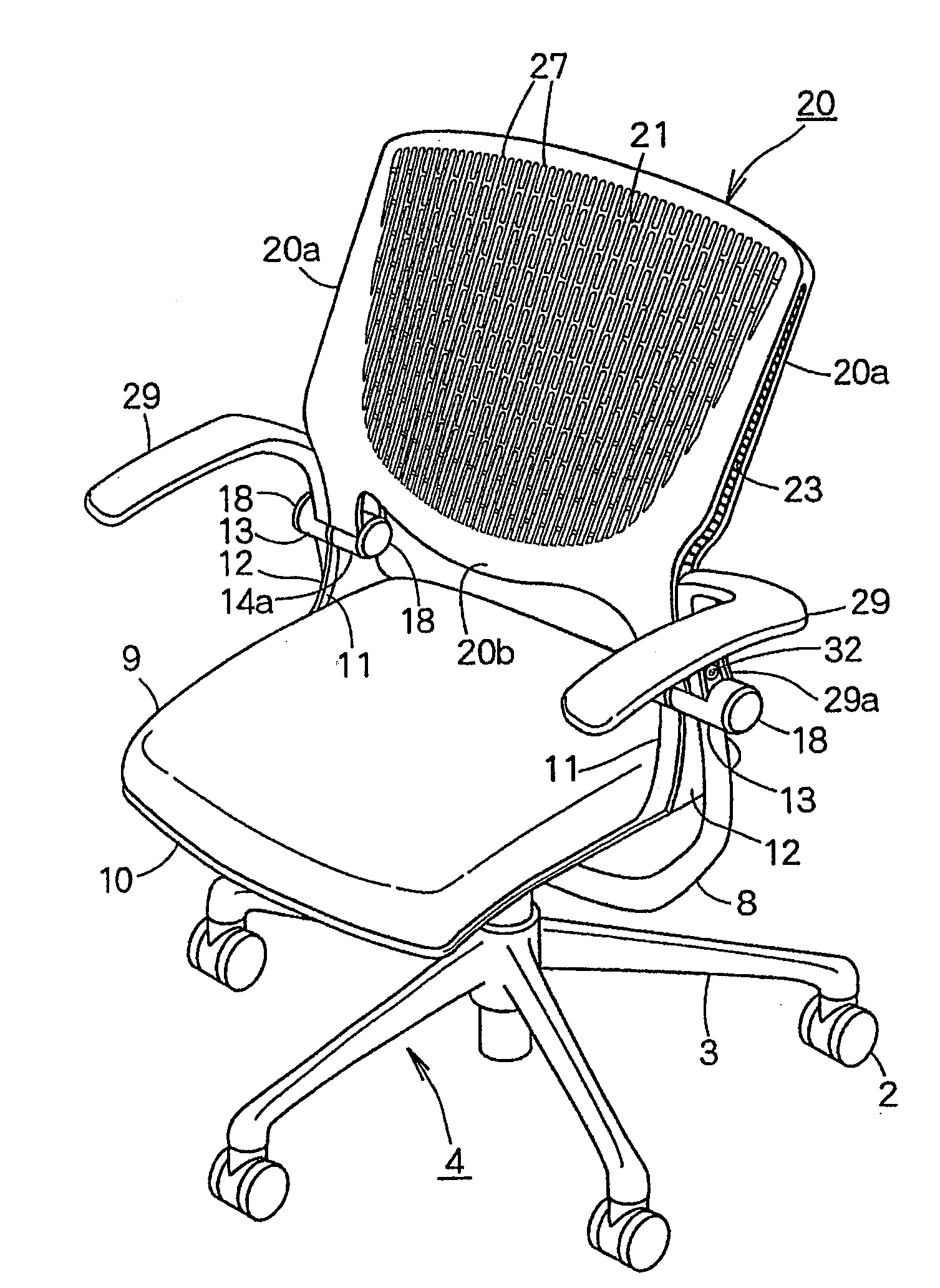
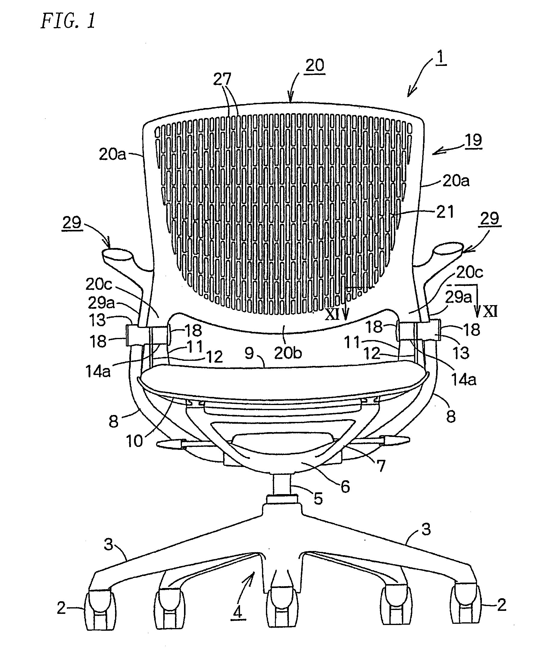
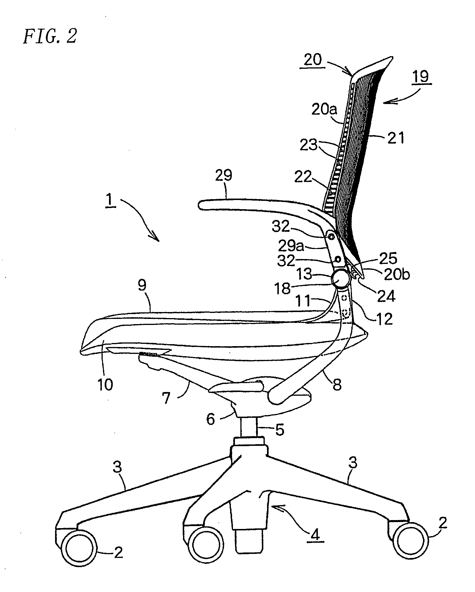
[0027]A chair 1 comprises a lower part 4 which consists of five legs 3 each of which has a caster 2 at the end; a post 5 which is retractable in the lower part 4 by a gas spring (not shown); and a support base 6 fixed to the upper end of the post 5.

[0028]A seat support frame 7 is integrally formed with and extends upward from the front end of the support base 6. A pair of backrest support rods 8,8 extends from the support base 6. In FIG. 5, a shaft 8a of each of the support rods 8,8 extends through a rubber torsion unit (not shown) in the support base 6 such that the support rods 8,8 are urged forward pivotally to move back and forth.

[0029]A cushion 9 is stretched over the upper surface of a seat 10. The seat 10 is supported by the seat support frame 7 to move back and forth. Each side of the rear end of the seat 10 is pivotally mounted to the upper end of the backrest support rod 8. Specifically, a pair of support portions 11,11 is provided at the upper ends of the rear ends of the...


PUM


Abstract

A backrest device for a chair, in which a backboard is easily flexible without a reduction in its strength, thus making the chair comfortable to sit on. The lower ends of both right and left sides of the back frame are supported at both sides at the back of a leg body, and the flexible back board is formed on the inside of rear frames. A large number of openings are formed in the backboard so as to be close to each other in the top-bottom and left-right directions. Between openings adjacent to each other in the left-right direction, there is formed a connection section continuing in the top-bottom direction, and the dimension in the front-back direction of the connection section is made larger than the dimension in the left-right direction of the connection section.

Description

BACKGROUND OF THE INVENTION[0001]The present invention relates to a backrest device in a chair and particularly relates to a backrest device in a chair comprising a flexible back plate for supporting the back of an occupant in a back frame supported by a leg.[0002]Such a backrest device in a chair is known from JP2002-125797A and JP2005-160558A.[0003]The backrest device in the publications disclose that a back frame and a back plate have nearly uniform thickness to make it impossible for an upper part of the back plate onto which the back of an occupant strongly presses to be bent rearward effectively. So the chair would not be comfortable to sit on.[0004]In order to allow the back of the occupant to fit over the backrest, the whole back plate may preferably be bent to be convex. But it would be very hard to bend a uniform-thickness back plate only by forming a number of opening in the back plate.[0005]A number of openings close to each other in the back plate would decrease bending...

Claims


Application Information

Patent Timeline
Patent Type & Authority Applications(United States)
IPC IPC(8): A47C7/40
CPCA47C7/44A47C7/40A47C7/445
Inventor IGARASHI, RYOTSUKIJI, HIROAKIMASUNAGA, HIROSHI
Owner OKAMURA CORP
Why Eureka
Try Eureka