Palatal expanders and methods of expanding a palate

a palatal expander and palate technology, applied in the field of palatal expanders, can solve the problems of impaired speech or difficulty, impossible deep breathing, and almost impossible without opening the mouth, and achieve the effect of reducing the retention or the ability of the palatal expander, and preventing or restricting gagging

Active Publication Date: 2022-03-15
ALIGN TECH
View PDF1234 Cites 13 Cited by
  • Summary
  • Abstract
  • Description
  • Claims
  • Application Information

AI Technical Summary

Benefits of technology

[0015]Also described herein are palatal expanders that are adapted for comfort to have a thickness that varies. For example, in any of these variations, the palatal expander may include an inner bottom surface in the palatal arch portion of the palatal expander that faces the patient' tongue when worn that is smooth or flattened compared to the opposite surface (matching the patient's palate where the palatal expander is worn. This tongue-facing side may have a surface that is rounded and does not include any rapid transitions in topology compared with the patient's actual palate. In any of these examples, the apparatuses described herein may have a different (including variable) thickness. In some variations, the apparatus may include a palatal region that is narrower toward the anterior of the palatal expander apparatus. In any of these variations, the poster portion of the palatal expander may be thinner and / or cut away (removed from) the palatal expander, which may prevent or limit gagging.
[0017]Also described herein are palatal expanders that are marked on a flat surface, e.g., a surface on the back or posterior edge of the palatal expander apparatus, with a code that indicates one or more of the series number (e.g., first, second, third, fourth, etc., holder, etc.), a patient code (e.g., identify the patient with specificity), a time and / or date, a copy number, etc. The identifying code or part number may be configured so that it may read by the user (e.g. patient) to assist in performing the palatal expansion in the proper sequence, as well as distinguishing between palatal expander and holder.
[0025]Any of these apparatuses may include a hinge (e.g., hinge region) on the buccal side or between the buccal side and the occlusal side that is configured permit bending at the hinge which may make removing the apparatus easier.
[0038]In general, any of these palatal expanders may be configured so that all or a portion (e.g., the mid-palatal region, e.g., configured to be positioned opposite of the suture) is spaced apart from the patient's palate when the device is worn, by some minimum distance, e.g., between 0.01 and 5 mm (e.g., 0.02 mm or greater, 0.03 mm or greater, 0.04 mm or greater, than 0.05 mm or greater, 0.06 mm or greater, 0.07 mm or greater, 0.1 mm or greater, 0.15 mm mm or greater, 0.2 mm or greater, 0.25 mm or greater, etc.) This minimum distance may be determined when forming the palatal expander by modeling (e.g., from a digital model) the patient's dental arch, including the palatal region. Including this minimal distance may be particularly helpful, for example, to prevent sores or irritation of the soft and / or hard palate when wearing the palatal expander(s).
[0051]In general, the first surface topography (e.g., the topography of the palatal-facing surface) may be configured to increase the structural integrity of the palatal region and provide between 8 and 160 N of force between the pair of tooth engagement regions when the device is worn by the patient. For example, the first surface topography may comprises a plurality of grooves and ridges configured to correspond to the grooves and ridges of the patient's palate. Alternatively or additionally, having the first surface topography correspond to the surface of the patient's palate may allow the palatal expander to sit on or adjacent (but offset from) the palatal expander more comfortably and / or closer than surface topographies with greater tongue clearance for an equivalent thickness of the palatal region than otherwise possible.

Problems solved by technology

In other cases there is room for the upper teeth but the palate is so narrow that speech is impaired or made difficult.
In other cases the palate is so high that it cuts down on the amount of air that can pass through the nose, so that deep breathing, without opening the mouth, is almost impossible.

Method used


Image

  • Palatal expanders and methods of expanding a palate
  • Palatal expanders and methods of expanding a palate
  • Palatal expanders and methods of expanding a palate

Examples


example 1

Treatment to Expand a Patient's Palate

[0193]The methods an apparatuses described herein may be used to treat young pre-pubertal subjects when a child's mouth has grown sufficiently to address the structure of the jaw and teeth while the primary teeth are still in the mouth. Palatal expansion may be used prior to aligner treatment; during this treatment, arch development occurs by increasing arch width or depth via dental or palatal expansion to create space for more permanent teeth to erupt. Typically aligners may not produce the required minimum transverse force needed for skeletal palatal expansion.

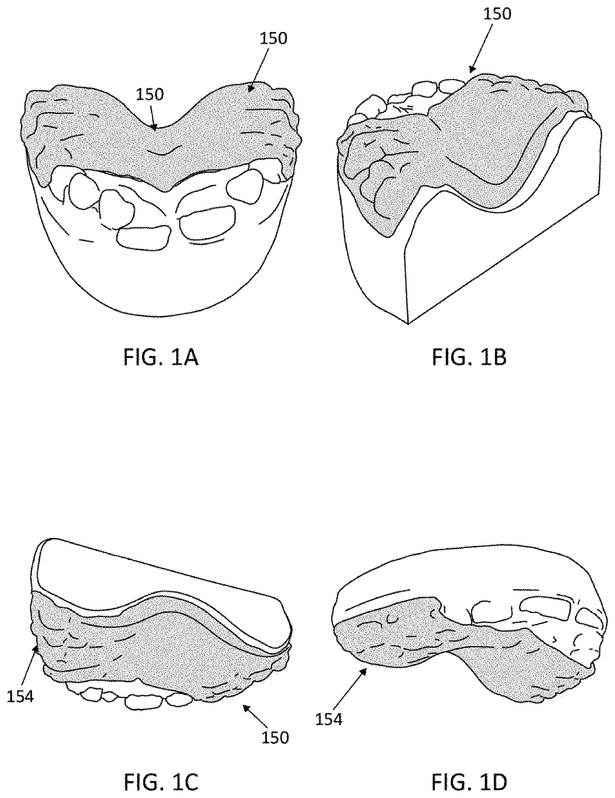
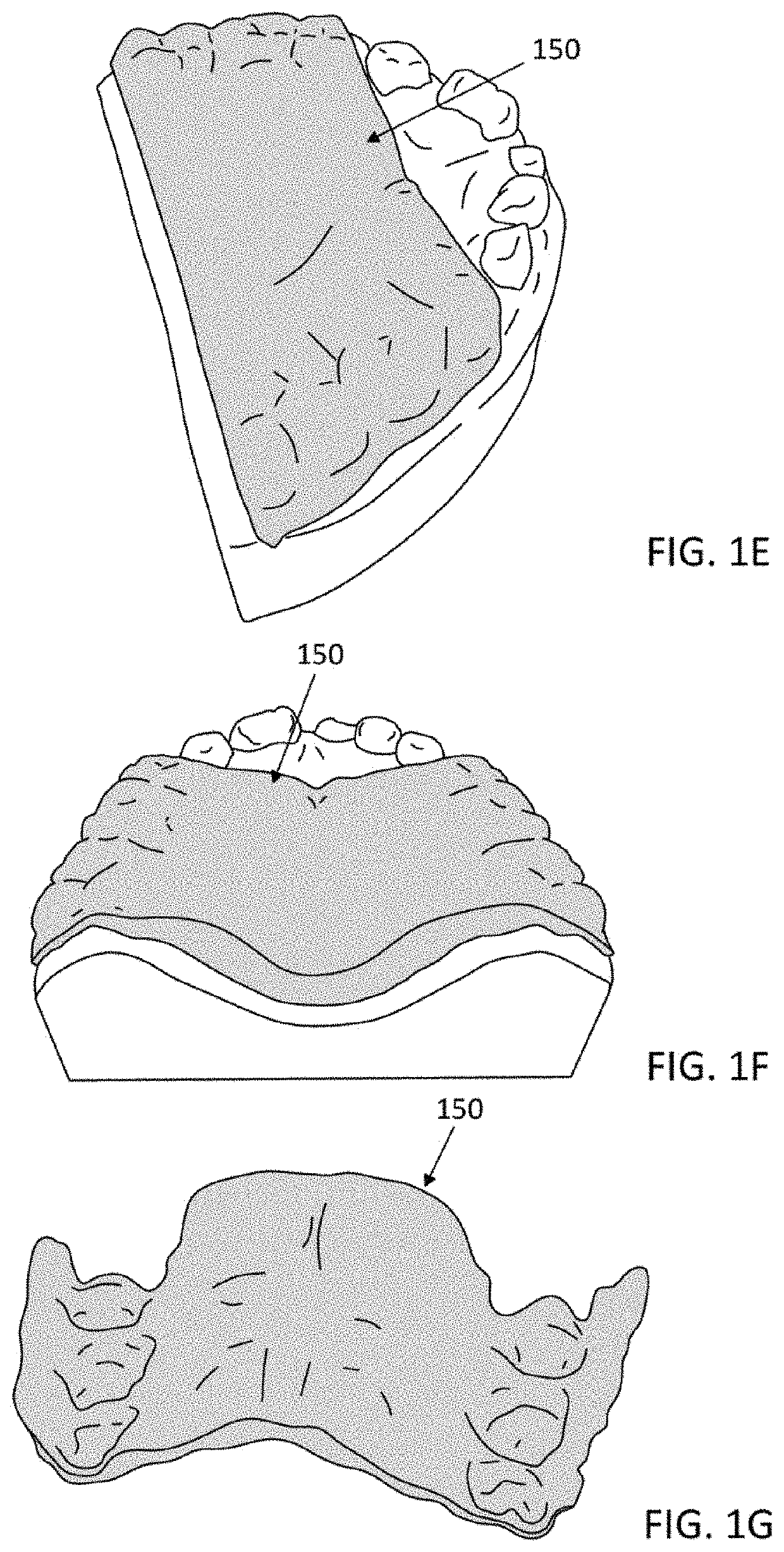
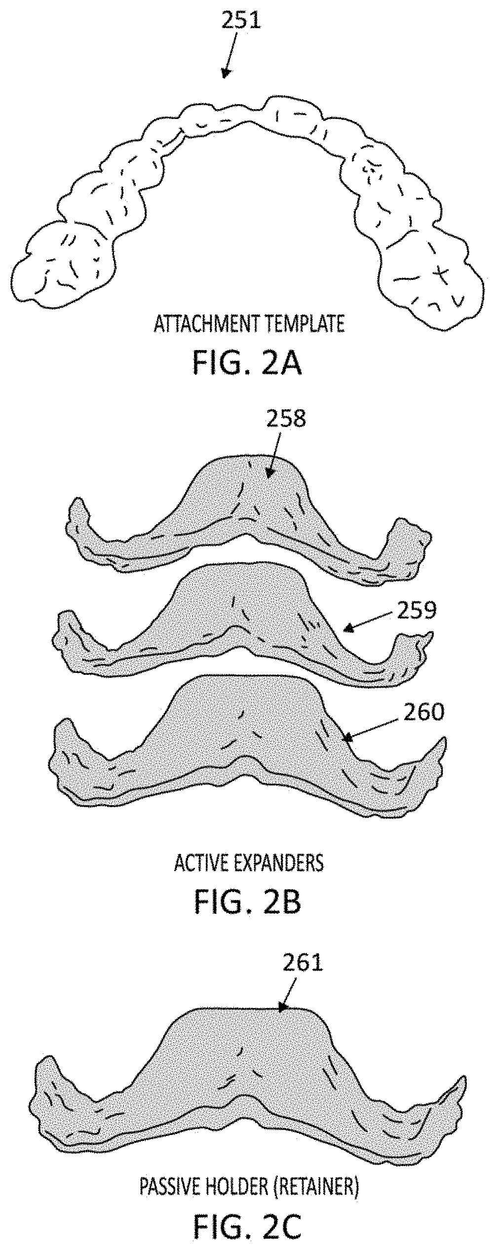
[0194]The palatal expander systems described herein may assist in skeletal and dental arch development. An example system may consist of a series of transpalatal arch feature that is intended to produce palatal expansion. The feature is designed to move / expand the palate by expanding the maxillary arch outwards buccolingually for transverse palatal size increases by exerting force on th...


PUM

PropertyMeasurementUnit
forceaaaaaaaaaa
forceaaaaaaaaaa
thickaaaaaaaaaa

Abstract

Palatal expander apparatuses for expanding a patient's palate (“palatal expanders”) and methods of using and making them. These palatal expanders may be configured to have a variable surface smoothness on one side (e.g., the lingual-facing surface) compared to the opposite side (e.g., the palatal-facing surface). These palatal expanders may be configured to have a varying thickness in the palatal region. These palatal expanders may be adapted for ease in removal by the patient or caregiver (e.g., including a hinged region and / or detachment region, and / or including a thinner buccal side then occlusal side, etc.).

Description

CROSS REFERENCE TO RELATED APPLICATIONS[0001]This patent application claims priority to U.S. Provisional Patent Application No. 62 / 429,692, filed on Dec. 2, 2016 (titled “METHODS OF FABRICATING PALATAL EXPANDERS”), and U.S. Provisional Patent Application No. 62 / 542,750, filed on Aug. 8, 2017 (titled “PALATAL EXPANDERS AND METHODS OF EXPANDING A PALATE”), each of which is herein incorporated by reference in its entirety. This patent application may also be related to U.S. patent application Ser. No. 15 / 831,262, titled “METHODS AND APPARATUSES FOR CUSTOMIZING A RAPID PALATAL EXPANDER” by Wu et al, concurrently filed herewith, which is also herein incorporated by reference in its entirety.[0002]This application may be related to US Patent Application Publication No. 2016 / 0081768 (titled “ARCH EXPANDING APPLIANCE”) and U.S. Patent Application Publication No. 2016 / 0081769 (titled “ARCH ADJUSTMENT APPLIANCE”), each of which is herein incorporated by reference in its entirety.INCORPORATION...

Claims


Application Information

Patent Timeline
Patent Type & Authority Patents(United States)
IPC IPC(8): A61C7/10A61C7/08A61C7/02A61C9/00B33Y50/02B33Y80/00B33Y10/00B29C64/393A61C7/00
CPCA61C7/10A61C7/002A61C7/023A61C7/08A61C9/00B29C64/393B33Y10/00B33Y50/02B33Y80/00
Inventor SHANJANI, YASERRILEY, JEREMYKIMURA, RYANSATO, JUNSU, NORMANCHENG, JIHUAWU, FUMING
Owner ALIGN TECH
Why Eureka
Try Eureka