
Method and apparatus for balancing a rotor

a rotor and rotor technology, applied in the direction of gearing, magnetic circuit shape/form/construction, instruments, etc., can solve the problems of difficult condition, large disturbing force, vibration, etc., and achieve the effect of improving rotor balancing

Active Publication Date: 2009-05-28
NUOVO PIGNONE TECH SRL
View PDF13 Cites 54 Cited by
  • Summary
  • Abstract
  • Description
  • Claims
  • Application Information

AI Technical Summary

Benefits of technology

[0007]Accordingly, there is a need for an improved rotor balancin

Problems solved by technology

This condition is quite difficult to achieve in the normal process of manufacturing since due to errors in geometrical dimensions and non-homogeneity of the material, some irregularities in the mass distribution are always present.
As a result of the above, variable disturbing forces occur which produce vibrations.
In such cases the slightest unbalance may produce a very large disturbing force.
The proper balancing of certain rotors, particularly for high-speed applications, requires unbalance correction not just in the end regions of the rotor but also in the midlength of the rotor body.
This highly stressed material cannot tolerate the stress concentrations caused by weight-addition or weight-removal features typically used for balancing.
This effectively restricts the size and speed that a rotor can operate.
This approach has limited effectiveness, as it does not address the unbalance caused during the assembly process.
Access to these regions is often restricted by the rotor support structure and the non-rotating machine components.

Method used


Image

  • Method and apparatus for balancing a rotor
  • Method and apparatus for balancing a rotor
  • Method and apparatus for balancing a rotor

Examples


Embodiment Construction

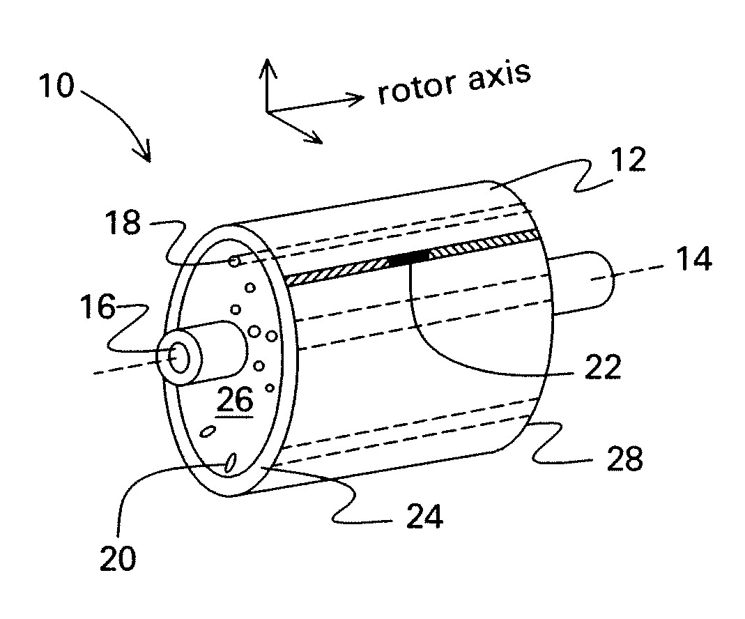
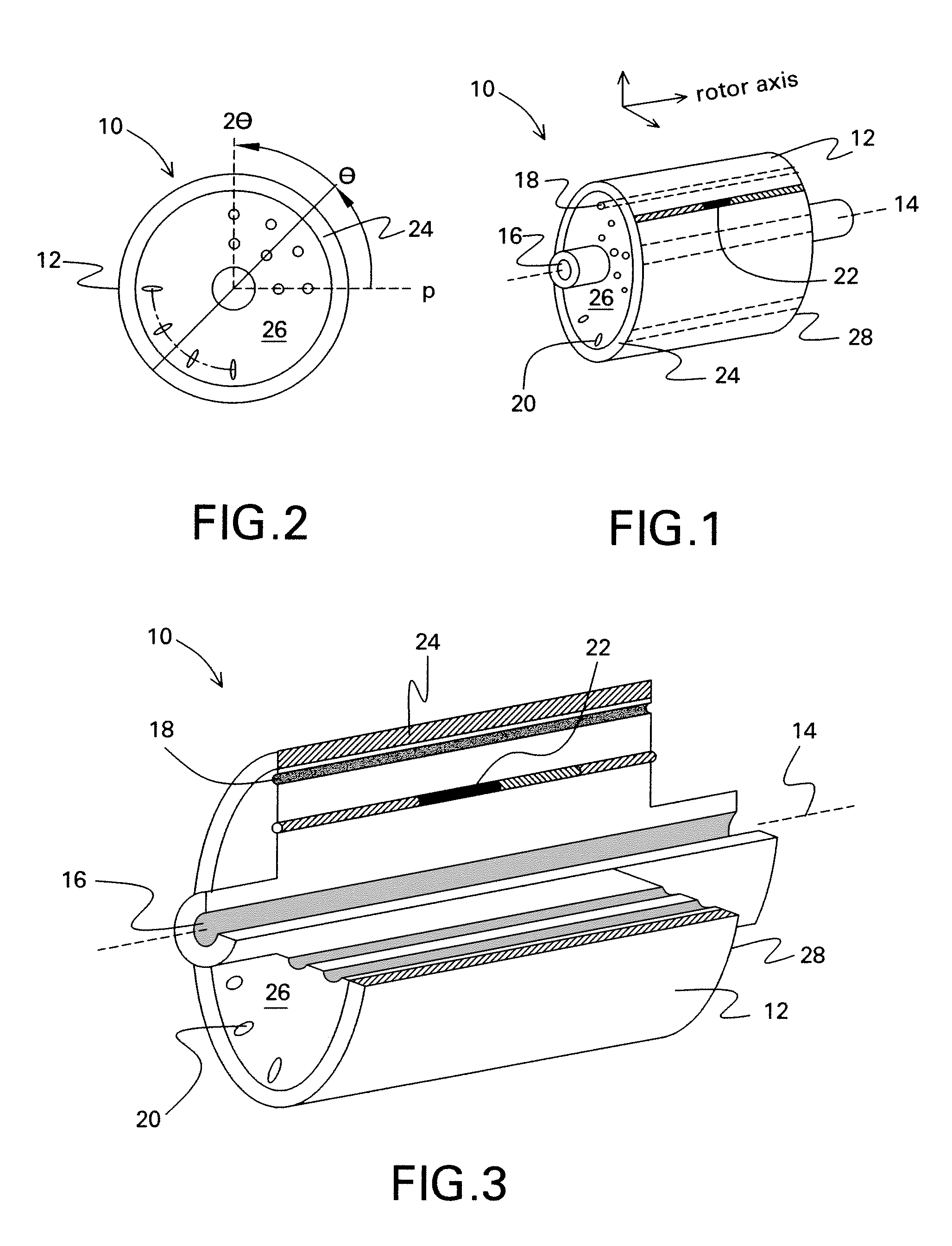
[0021]A midlength balanced rotor 10 comprises a rotor assembly 12 for rotation about an axis of rotation 14 defining at least one of an axially extended, radially concentric, centerline borehole 16, an array of radially or tangentially distributed, axially extended pockets 18, and a series of radially or tangentially distributed, axially extended slots 20, and at least one balance weight 22 disposed within at least one of the borehole 16, a respective pocket 18, or a respective slot 20, is shown in FIGS. 1 and 2.

[0022]As discussed above, common rotor architectures, especially in high-speed applications, make use of an outer shell 24 of material that is highly stressed. This highly stressed material cannot tolerate the stress concentrations caused by weight-addition or weight-removal features typically used for balancing. Accordingly, the only locations available for balancing rotors of this configuration have traditionally been in the end regions 26, 28 of the rotor assembly 12 wher...


PUM


Abstract

A midlength balanced rotor comprises a rotor assembly for rotation about an axis of rotation defining at least one of an axially extended, radially concentric, centerline borehole; an array of radially or tangentially distributed, axially extended pockets; and a series of radially or tangentially distributed, axially extended slots. At least one balance weight is positioned within at least one of the axially extended, radially concentric, centerline borehole, the array of radially or tangentially distributed, axially extended pockets, or the radially or tangentially distributed, axially extended slots to balance the rotor assembly. Alternatively, at least one balance correcting mass is removed from at least one of the axially extended, radially concentric, centerline borehole, the array of radially or tangentially distributed, axially extended pockets, or the radially or tangentially distributed, axially extended slots to balance the rotor assembly. In addition, a method of midlength balancing a rotor comprises the steps of providing a rotor assembly with at least one of an axially extended, radially concentric, centerline borehole; an array of radially or tangentially distributed, axially extended pockets; and a series of radially or tangentially distributed, axially extended slots; rotating the rotor shaft about an axis of rotation; determining unbalance of the rotor shaft; and adding or removing weight to at least one of said an axially extended, radially concentric, centerline borehole; array of radially or tangentially distributed, axially extended pockets; or series of radially or tangentially distributed, axially extended slots, to balance the rotor shaft.

Description

BACKGROUND[0001]The invention relates generally to methods and apparatus for balancing a rotor and more specifically to methods and apparatus for midlength balancing of a rotor.[0002]A rotating body will not exert any variable disturbing force on its supports when the axis of rotation coincides with one of the principal axes of inertia of the body. This condition is quite difficult to achieve in the normal process of manufacturing since due to errors in geometrical dimensions and non-homogeneity of the material, some irregularities in the mass distribution are always present.[0003]As a result of the above, variable disturbing forces occur which produce vibrations. To remove these vibrations and establish safe and quiet operation, balancing becomes necessary. The importance of balancing becomes especially great in the case of high-speed machines, for example a turbine rotor or electric machinery that operates at speeds typical of turbomachinery. In such cases the slightest unbalance ...

Claims


Application Information

Patent Timeline
IPC IPC(8): G01M1/20
CPCY10T74/22G01M1/36
Inventor VAN DAM, JEREMY DANIELKAMINSKI, CHRISTOPHER ANTHONYWILSON, BLAKE WELDON
Owner NUOVO PIGNONE TECH SRL
Learn More