Refuse Chute

Inactive Publication Date: 2009-05-28
PRESTON JOHN CLEMENT
View PDF14 Cites 9 Cited by
  • Summary
  • Abstract
  • Description
  • Claims
  • Application Information

AI Technical Summary

Benefits of technology

[0014]The internal baffles provide protection from refuse falling from above, so that a user may safely put refuse in the chute at lower levels with minimal chance that refuse falling from above can harm them. It is desirable that the baffle length be equal to or longer than an average person's arm so as to protect the person and arm of the person from refuse falling from above.
[0015]Preferably, a chute section may have multiple openings along the height thereof, thereby providing different refuse insertion locations for disposal of refuse. So, for example, a person seeking to dispose of refuse does not have to bend over or lift it up to an opening location above floor level, and may instead use an inlet at a lower height along the chute section, eg one at floor level, thereby enabling refuse to be simply swept into the chute.
[0016]Preferably, the angle and the distance that the baffle extends into the disposal shaft are chosen such that the baffle provides an awning for the opening below the opening with which the baffle is associated. Even more preferably, the end of the baffle distal to the opening with which it is associated is on a horizontal plane and with

Problems solved by technology

Such entry point is at a fixed location on the chute section, so the refuse may need lifting or lowerin

Method used


Image

  • Refuse Chute
  • Refuse Chute
  • Refuse Chute

Examples


Embodiment Construction

[0031]The present invention may be implemented in a variety of ways and the embodiments illustrated are to be considered only illustrative constructions.

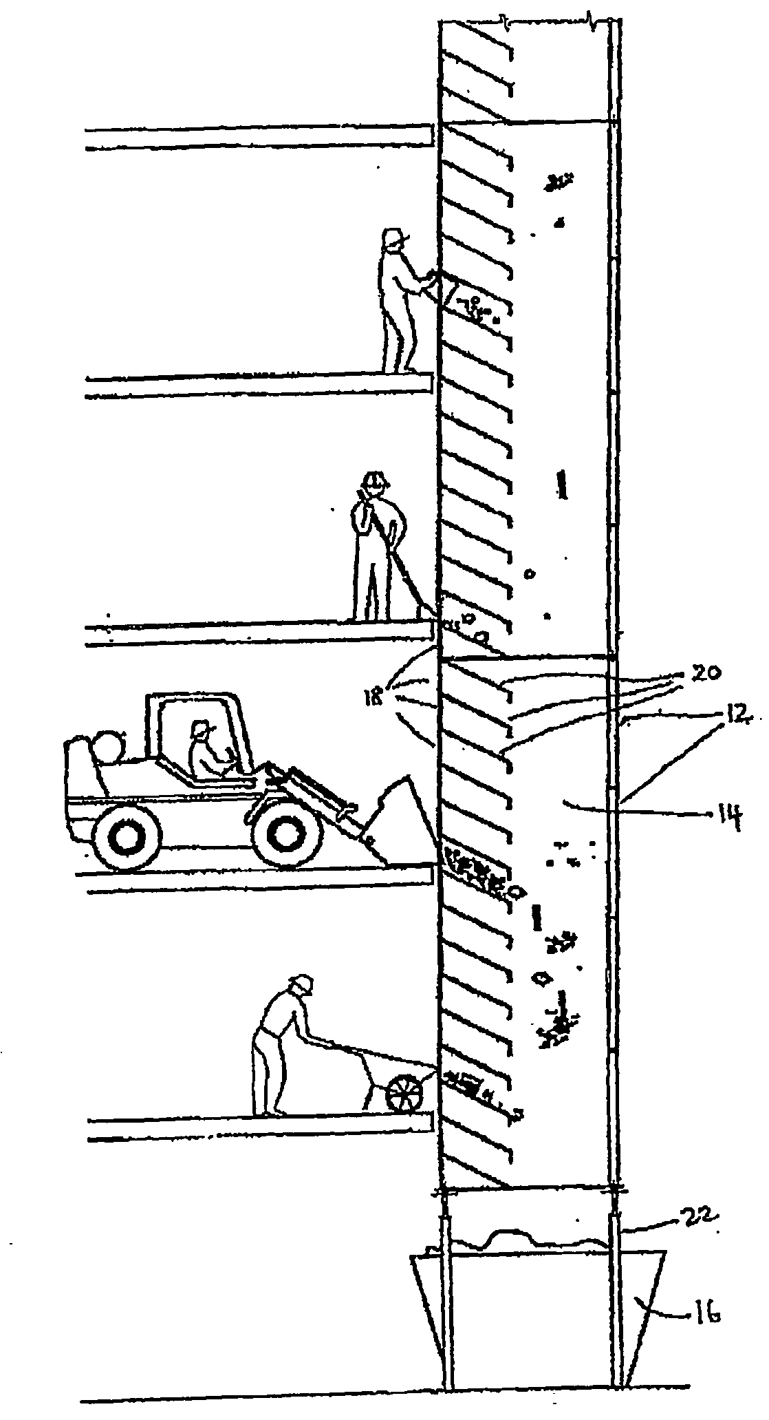
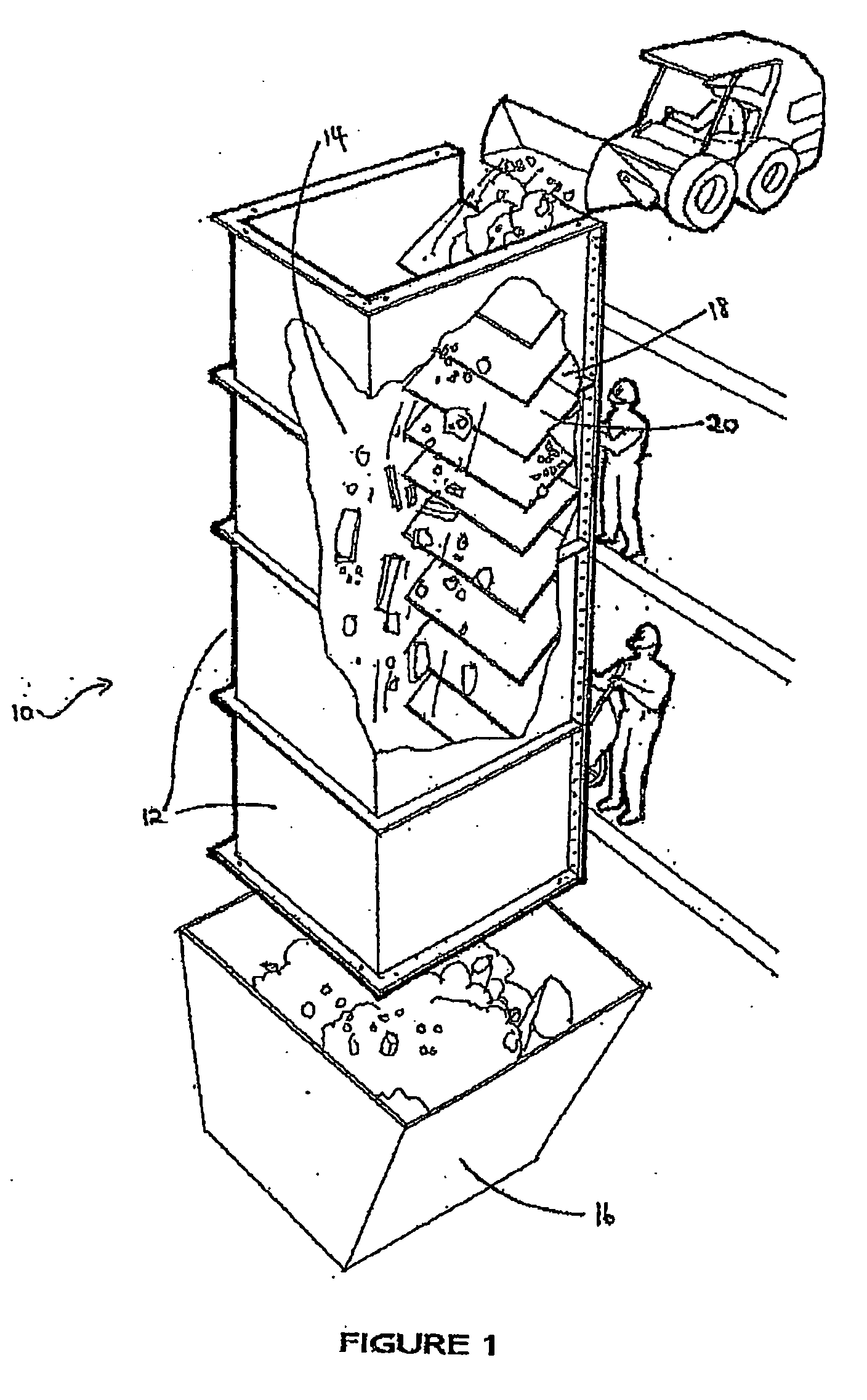
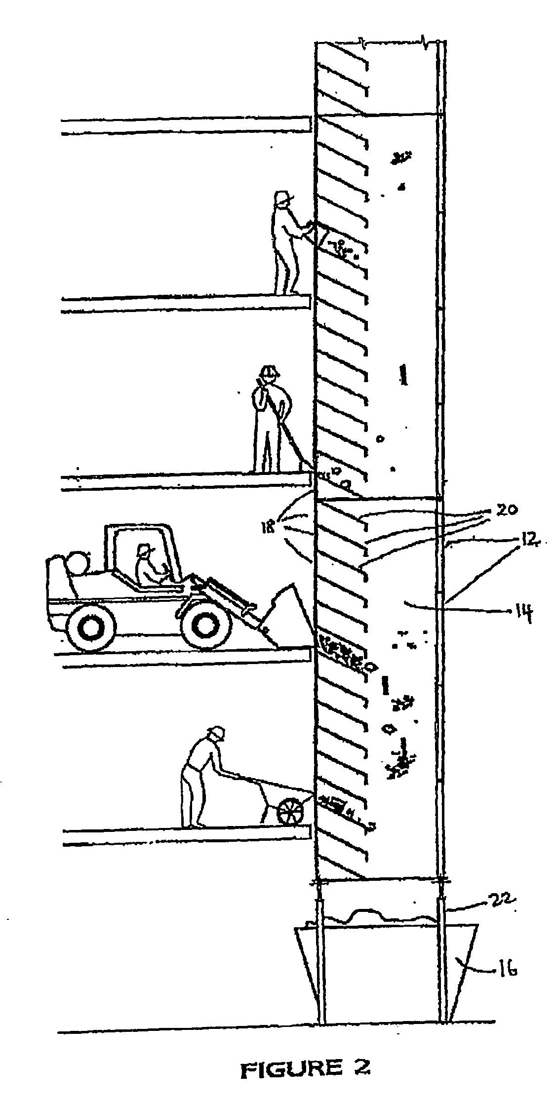
[0032]FIG. 1 is a schematic perspective view of the refuse chute 10. Refuse chute 10 is assembled from four identical chute sections 12. The chute sections 12 may be identical and stacked and secured together at the end faces, as shown, or be of some other configuration such as a nesting arrangement in which the chute sections are joined together through their side walls, ie similar to telescopically inserted sections. The chute sections 12 can be stacked as high as needed for the particular application. Different types of chute sections are known from, for example, GB 2,229,427 A, U.S. Pat. No. 3,627,090, and AU 682758, the contents of which are hereby incorporated by reference.

[0033]In this case, the chute sections 12 are of constant quadrilateral cross-section, made of steel sheets, and removably joined together at their end face...


PUM


Abstract

A refuse chute for a building assembled from a plurality of tubular chute sections, the chute sections being stackable in an end-to-end or end-wise nesting relationship and securable to provide an enclosed refuse disposal shaft, at least some of the chute sections having one or more openings in a side wall of the chute section, characterised in that a baffle each is associated with one or more of the openings, the baffle extending from the side wall into the disposal shaft and being preferably inclined such that there is an obtuse angle between the baffle and the opening with which the baffle is associated. A refuse chute section is also claimed.

Description

FIELD OF THE INVENTION[0001]The present invention relates to a refuse chute for gravity disposal of refuse from storeys of a multi-storey building such as during building construction or refurbishment.BACKGROUND OF THE INVENTION[0002]It is normal practice on multi-storey building sites to provide for the removal of refuse from upper floors of a building by a refuse chute which defines a shaft whereby all types of building refuse may be dropped from the upper floors down the chute shaft to a container located at the bottom of the chute, eg at ground level.[0003]Such chutes are usually assembled from individual tubular sections of circular or quadrilateral cross-section which are stackable to provide a height suitable to the specific building. The individual sections which, when in place, extend vertically along the building have one or more refuse inlet structures that enable a user to put refuse into the chute for gravity disposal. As such, conventional refuse chutes have many adjus...

Claims


Application Information

Patent Timeline
IPC IPC(8): E04F17/12
CPCB65F1/0093E04F17/12B65G11/026B65F5/00
Inventor PRESTON, JOHN CLEMENT
Owner PRESTON JOHN CLEMENT
Why Eureka
Try Eureka