Launcher for a toy glider

Inactive Publication Date: 2009-05-28
OREN SALOMON CLARK
View PDF2 Cites 1 Cited by
  • Summary
  • Abstract
  • Description
  • Claims
  • Application Information

AI Technical Summary

Benefits of technology

[0009]A primary object of the present invention is to offer the consumer an

Problems solved by technology

However, his designs required human

Method used


Image

  • Launcher for a toy glider
  • Launcher for a toy glider
  • Launcher for a toy glider

Examples


Embodiment Construction

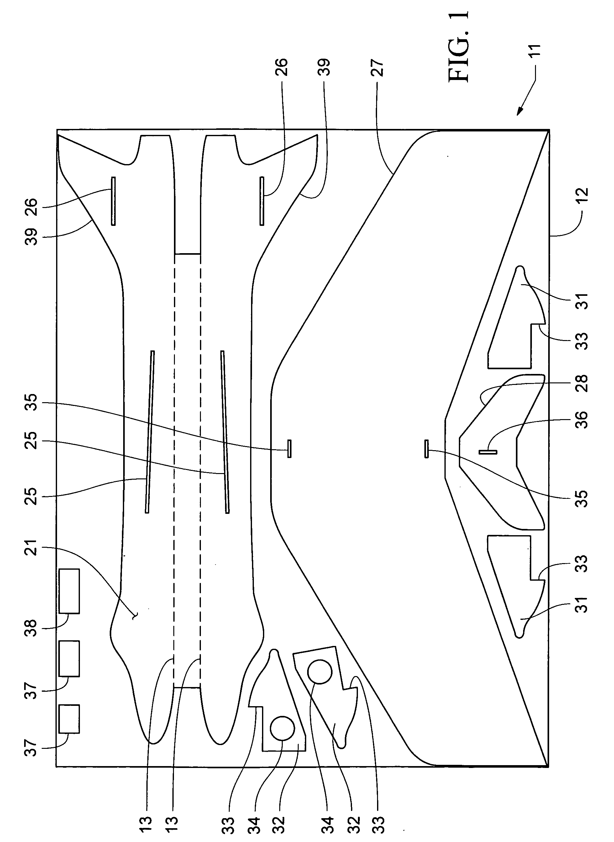
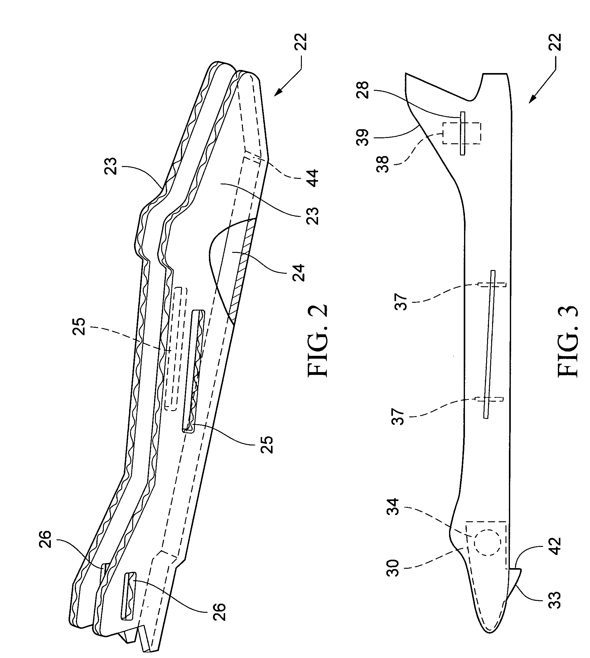
[0029]FIG. 1 is an illustration of a typical glider parts layout 11, in a sheet of corrugated paperboard 12, showing the patterned design in a pre-cut punch-out format. A couple of coins, or something with a similar weight, and some glue are all that are necessary to make the completed glider 10, shown in FIGS. 3, 4, and 5. The fuselage pattern 21, when folded along visibly scored guide lines 13, transforms into a three sided, “U” shaped beam 22 forming two uprights 23 and a bottom 24, as best illustrated in FIG. 2. The “U” shape provides the fuselage with built-in stiffness and cross-sectional strength. The two uprights 23 have the same profile, showing the silhouette and reproduction of the glider model on its outside surfaces. Each upright has cutout slots, positioned in line, for inserting a wing 27 through slots 25 and a horizontal stabilizer 28 through slots 26. Score lines at each wing tip provides fine-tuning of the glider's flying performance.

[0030]An interposing weight pac...


PUM


Abstract

A method for making an affordable toy glider and launcher with intrinsic cross-sectional strength and extended useful life, each made from a sheet of corrugated paperboard. The sheets have a patterned layout of a complete set of glider and launcher parts that are printed on a printable side of the corrugated paperboard. All parts are precut and retained in place. The central body (fuselage) has two mirror imaged sides foldable along scored guide lines to form a three sided “U” shaped structure. A nose pack with coin weights used for balance, is placed at the nose section between the sides. A wing and stabilizer cutouts are inserted in slots with tabs used to center and fix the cutouts in place. Included is a pistol grip launcher which is universal in its use for launching all types of toy gliders.

Description

[0001]This is a Divisional application of pending U.S. patent application Ser. No. 10 / 096,977, filed on Mar. 13, 2002, which is herein incorporated by reference in its entirety.BACKGROUND OF THE INVENTION[0002](1) Technical Field[0003]This invention relates generally to toys that fly, and more particularly, to a hand launched gliding apparatus. It also relates to a launching apparatus.[0004](2) Description of the Prior Art[0005]The ability to fly like a bird is an ancient aspiration of mankind. The first person to take a scientific approach to human flight was Leonardo Da Vinci. His designs included three types of aircraft, the omithopter, helicopter, and glider. However, his designs required human power to fly, thus was impractical.[0006]Building and flying stick models has been and still is an excellent way to learn about glider construction and the basics of flying objects. This is the method used by aviation's pioneers, and the skill is still basic to building free flight and ra...

Claims


Application Information

Patent Timeline
IPC IPC(8): A63H27/14
CPCA63H27/02A63H27/001
Inventor CLARK, OREN SALOMON
Owner OREN SALOMON CLARK
Why Eureka
Try Eureka