Unlock instant, AI-driven research and patent intelligence for your innovation.

Article Alignment Apparatus

a technology of alignment apparatus and box-shaped articles, which is applied in the field of article alignment apparatus, can solve the problems of difficult to reliably move the center of gravity of box-shaped articles, difficult to stably and reliably align the orientation of box-shaped articles, and difficult to align the articles in a certain orientation

Inactive Publication Date: 2009-06-04
KAO CORP
View PDF6 Cites 1 Cited by
  • Summary
  • Abstract
  • Description
  • Claims
  • Application Information

AI Technical Summary

Benefits of technology

[0009]According to the invention, there is provided an article alignment apparatus comprising at least one aligner having rotary cylindrical surfaces with protrusions, wherein the aligner slants at a predetermined inclination with respect to a horizontal direction so that the aligner is capable of aligning an article on its surface by placing the articles on the cylindrical outer surfaces of the aligner, so that the articles are movable from one end to the other end of the aligner.

Problems solved by technology

However, in the article alignment apparatus in Patent Document 1, the box-shaped article slips against the cylindrical face of the rotating gutter-shaped member and it is difficult to reliably move the center of gravity of the box-shaped article in the above-described manner as the gutter-shaped member rotates and it is difficult to stably and reliably align orientations of the box-shaped articles.
However, if the article alignment apparatus in Patent Document 2 tries to align cylindrical articles with top faces such as caps which are not the long-columnar articles with heads, it is difficult to align the articles in a certain orientation, though it is possible to space the articles from each other.

Method used


Image

  • Article Alignment Apparatus
  • Article Alignment Apparatus
  • Article Alignment Apparatus

Examples


embodiment 1-1

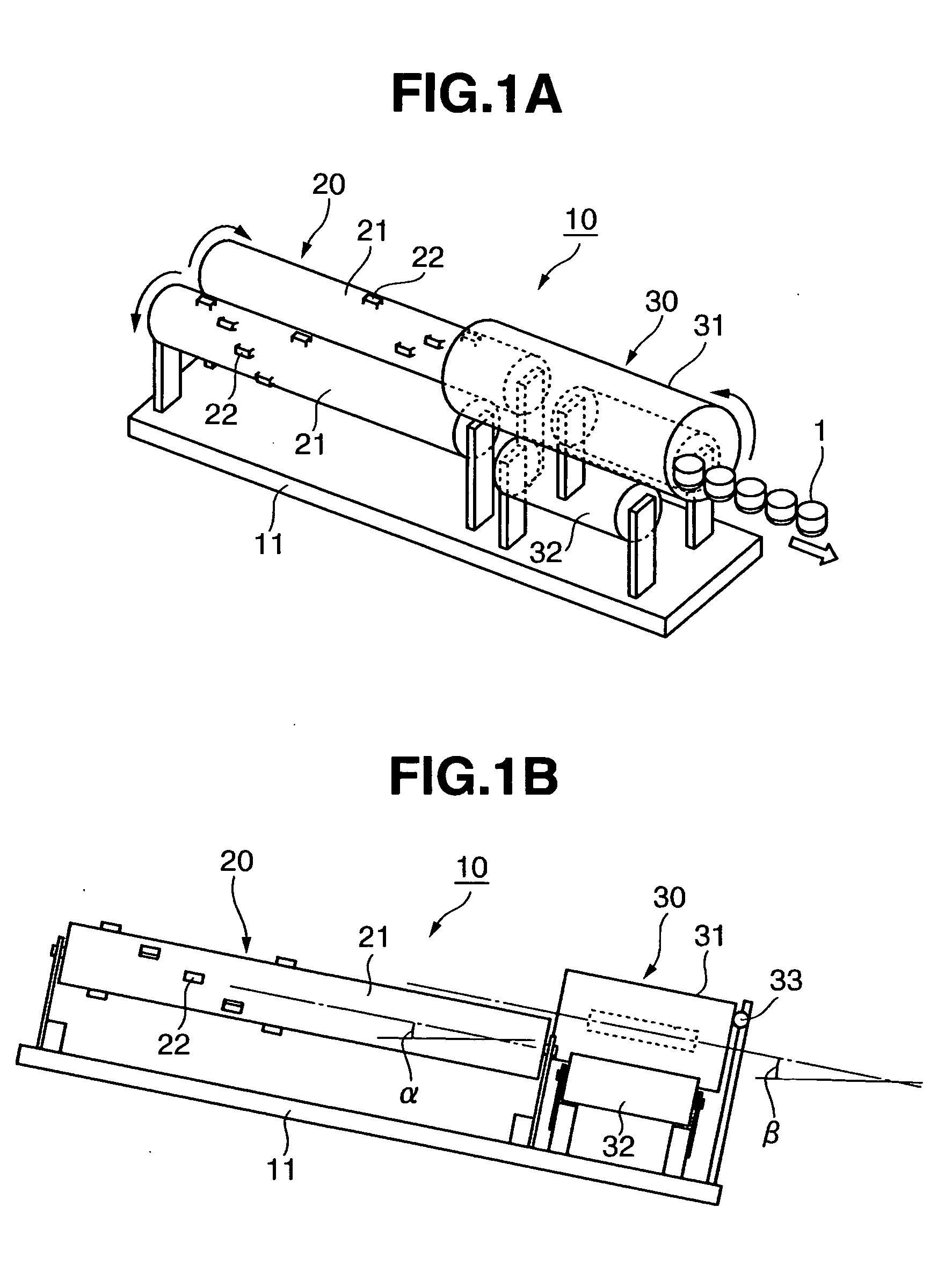
[0074]In a configuration shown in FIGS. 1A and 1B, without providing the second article alignment device 30 and by using only the first article alignment device 20, circular caps 1 were aligned. In a position where the second article alignment device 30 should exist, a conveyer properly regulated to a discharge speed of the caps 1 was disposed (not shown). A target attitude was an attitude with an open face up and most of the caps 1 could be aligned. The surfaces of the aligners 21 of the first article alignment device 20 were given uni-chrome plating that is a very general method of treating a metal surface.

embodiment 1-2

[0075]In the configuration shown in FIGS. 1A and 1B, without providing the second article alignment device 30 and by using only the first article alignment device 20, circular caps 1 were aligned. In a position where the second article alignment device 30 should exist, a conveyer properly regulated to a discharge speed of the caps 1 was disposed (not shown). A target attitude was an attitude with an open face up and most of the caps 1 could be aligned. The surfaces of the aligners 21 of the first article alignment device 20 were subjected to the friction reducing treatment in which the adhesive tape made of fluorocarbon resin and manufactured by Chukoh Chemical Industries, Ltd. was stuck on the surfaces and inclinations were also reduced. As a result, the throughput was slightly enhanced and the alignment efficiency was enhanced considerably as compared with that in the embodiment 1-1.

embodiment 2

[0076]In the configuration shown in FIGS. 1A and 1B, without providing the second article alignment device 30 and by using only the first article alignment device 20, oval caps 1 were aligned. In a position where the second article alignment device 30 should exist, a conveyer properly regulated to a discharge speed of the caps 1 was disposed (not shown). A target attitude was an attitude with an open face up and most of the caps 1 could be aligned.


PUM


Abstract

There is provided an article alignment apparatus 10 including an article alignment device for aligning orientations of articles by arranging two aligners 21, 21 having cylindrical surfaces, rotating each of the aligners 21 while keeping it at a predetermined inclination with respect to a horizontal direction, placing the articles on cylindrical outer surfaces of the two aligners 21, and carrying the articles from one side to the other side, in which protrusions 22 are provided on the surfaces of the aligners 21.

Description

FIELD OF THE INVENTION[0001]The present invention relates to an article alignment apparatus.BACKGROUND OF THE INVENTION[0002]Conventionally, in filling and capping equipment for filling liquid into a container and capping the container, a cap alignment apparatus (article alignment apparatus) for aligning and feeding caps in various forms is used.[0003]There is an article alignment apparatus as disclosed in Japanese Patent Publication (JP-A) No. 51-47753 (Patent Document 1) in which a cylindrical gutter-shaped member is inclined and rotated and box-shaped articles are put into the gutter-shaped member and are carried from one side to the other side to thereby bring the articles into balanced attitudes and, as a result, align orientations of the articles.[0004]There is an article alignment apparatus as disclosed in Japanese Patent Publication (JP-A) No. 2004-168542 (Patent Document 2) in which, in arranging two columns parallel while inclining them and rotating the columns in reverse ...

Claims


Application Information

Patent Timeline
IPC IPC(8): B65G47/14
CPCB65G47/1492B67B2201/06B65G47/24
Inventor HATANO, KOUICHIISHIGAWA, JUNICHISUZUKI, MASAAKISHIRAI, HIDENORI
Owner KAO CORP
Features
  • R&D
  • Intellectual Property
  • Life Sciences
  • Materials
  • Tech Scout
  • Unparalleled Data Quality
  • Higher Quality Content
  • 60% Fewer Hallucinations
Learn More