Variable volume toner replenisher dispenser for tipp systems
Inactive Publication Date: 2009-06-04
XEROX CORP
View PDF5 Cites 3 Cited by
Summary
Abstract
Description
Claims
Application Information
AI Technical Summary
This helps you quickly interpret patents by identifying the three key elements:
Problems solved by technology
Method used
Benefits of technology
[0007]Conventional printing systems can include multiple marking engines, multiple media paths, and one or more multiple destinations. Printing systems may also include multiple toner/replenisher supply stations. In xerographic Tightly Integrated Parallel Processing (TIPP) systems, these toner/replenisher supply stations often require regular attention. Whenever a toner/replenisher supply bottle runs low in a printing system it must be replaced in order to continue printing. This problem becomes more defined in TIPP systems. For example, a two engine black and white TIPP xerographic system would require monitoring in each system. Therefore, two e
Problems solved by technology
The problem, however, becomes more difficult with the more engines in the TIPP system.
Without an improved design or service strategy, the operator will be required to very frequently interact with the printer in order to add toner/replenisher.
The solution could become impractical as the number of engines grows.
Furthermore, the plumbing sys
Method used
Image
Click on the blue label to locate the original text in one second.
Reading with bidirectional positioning of images and text.
Examples
Example
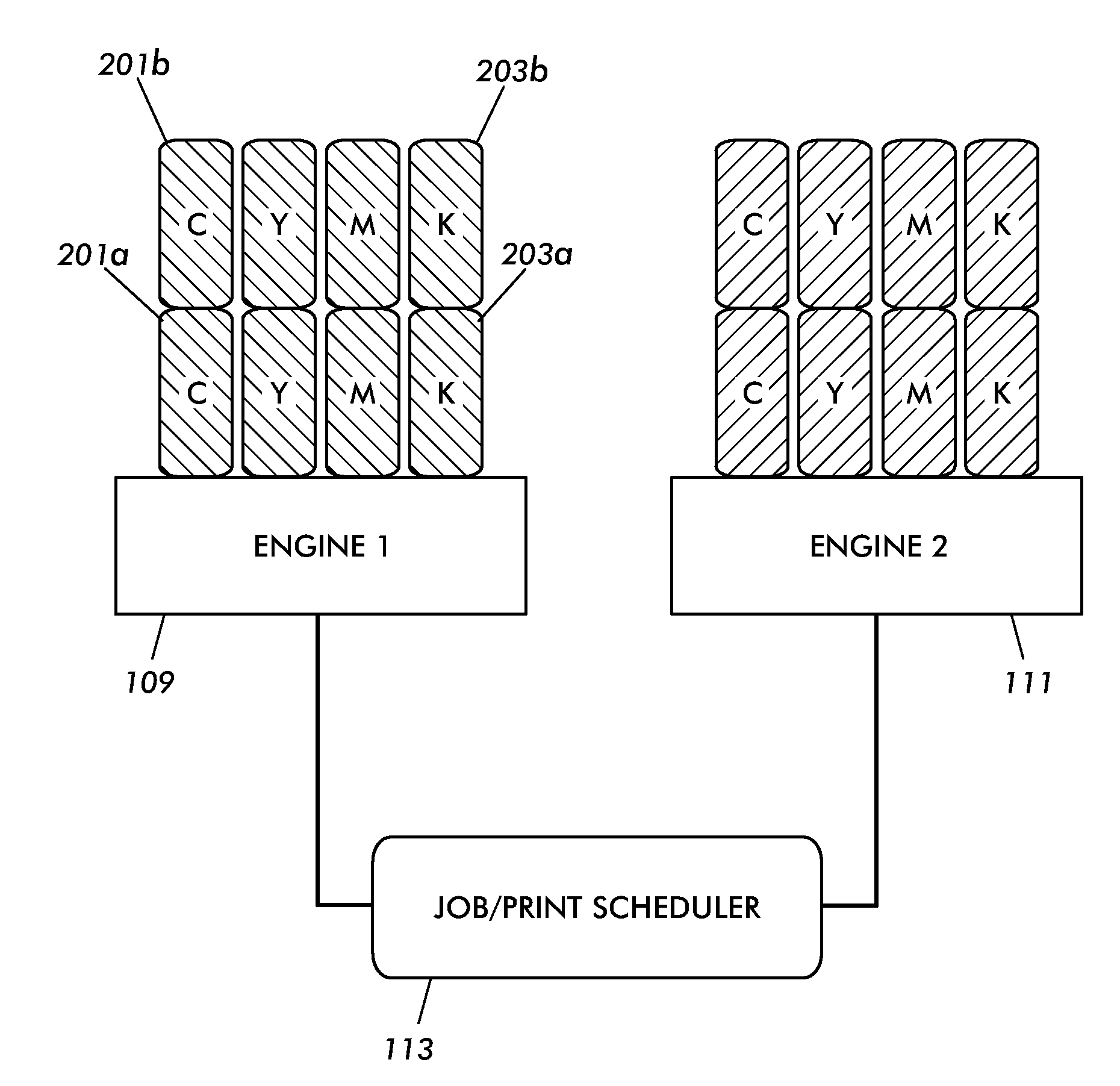
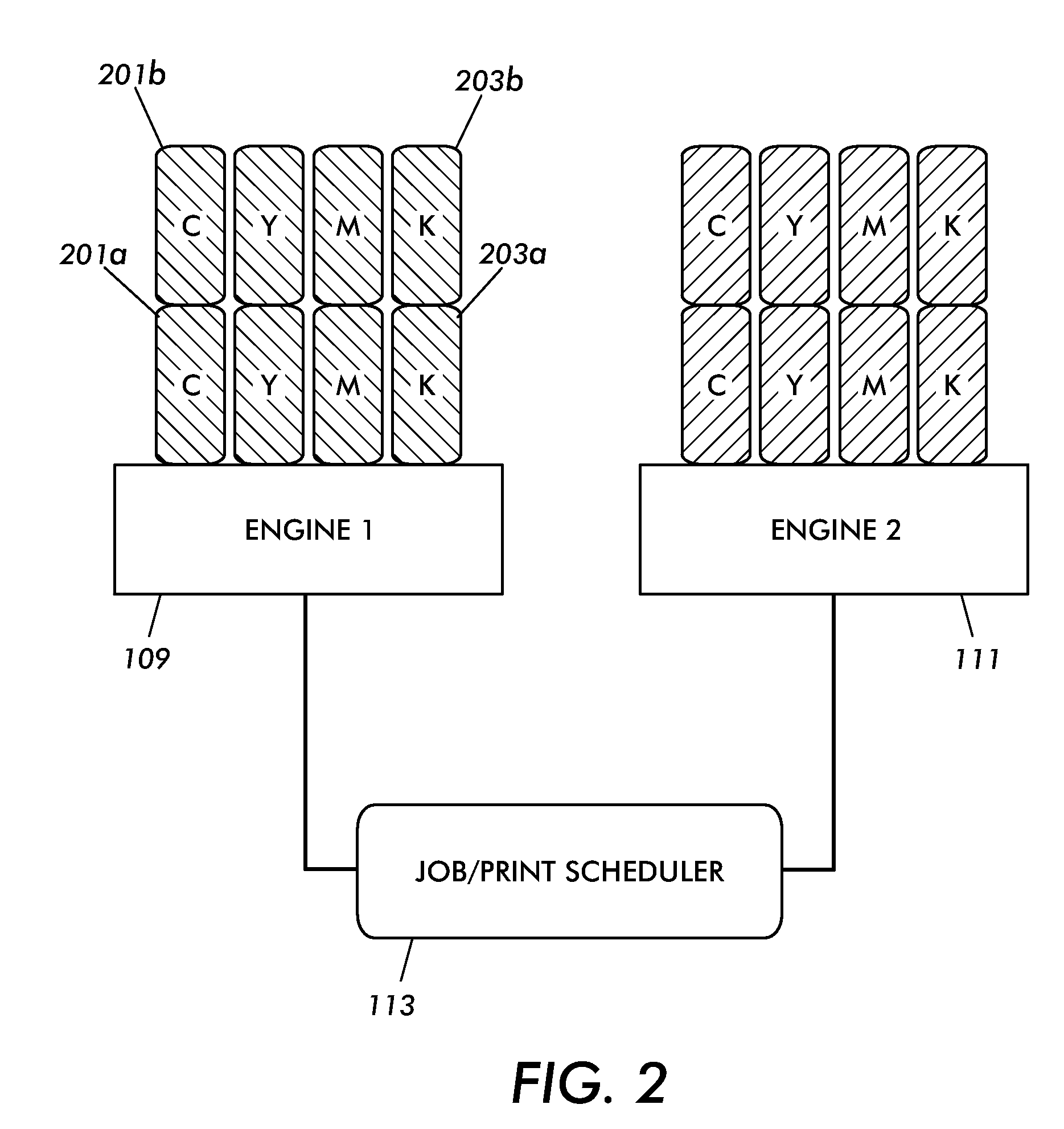
[0016]As disclosed in more detail below, this disclosure relates to an assembly that has a dispenser supply system that includes multiple bottles for each color for each printing engine in a printing system. This disclosure would allow for toner / replenisher to either exit from the bottom of the bottle, enter through the top of the bottle, or both. The general concept would include a series of bottles configured to interlock from top to bottom. Each set of bottles has a sensor detecting the system fill level. The system also has a master sensor that provides a signal to the customer when one of the sets requires an intervention. The operator may then refill all of the sets for each color, for each engine. In this sense, the system continues to operate until the next “required” intervention is reached. This overall strategy minimizes the amount of interventions required by a customer or operator and helps ensure that all toner / replenisher is used from each bottle. The system may be em...
PUM
Abstract
A printing fluid dispenser system for multi-printer engine assembly is disclosed. The system includes a first dispenser that is adjacent to the print engine that is configured to pass printing fluid to an associated printing engine, a second dispenser adjacent to the first dispenser that is configured to store the printing fluid and pass the printing fluid to the first dispenser as the first dispenser passes the printing fluid to the printing engine and a sensor configured to detect when the printing fluid remaining in one of the first or second dispensers drops below a predetermined threshold.
Description
CROSS REFERENCE TO RELATED PATENTS AND APPLICATIONS[0001]The following applications, the disclosure of each being totally incorporated herein by reference as mentioned.[0002]U.S. Publication No. US-2006-0114497-A1 (Attorney Docket No. 20031830-US-NP), Published Jun. 1, 2006, entitled “PRINTING SYSTEM,” by David G. Anderson, et al., and claiming priority to U.S. Provisional Application Ser. No. 60 / 631,651, filed Nov. 30, 2004, entitled “TIGHTLY INTEGRATED PARALLEL PRINTING ARCHITECTURE MAKING USE OF COMBINED COLOR AND MONOCHROME ENGINES”;[0003]U.S. Publication No. US-2006-0067756-A1 (Attorney Docket No. 20031867Q-US-NP), filed Sep. 27, 2005, entitled “PRINTING SYSTEM,” by David G. Anderson, et al., and claiming priority to U.S. Provisional Patent Application Ser. No. 60 / 631,918 (Attorney Docket No. 20031867-US-PSP), filed Nov. 30, 2004, entitled “PRINTING SYSTEM WITH MULTIPLE OPERATIONS FOR FINAL APPEARANCE AND PERMANENCE,” and U.S. Provisional Patent Application Ser. No. 60 / 631,921,...
Claims
Application Information
Patent Timeline
Application Date:The date an application was filed.
Publication Date:The date a patent or application was officially published.
First Publication Date:The earliest publication date of a patent with the same application number.
Issue Date:Publication date of the patent grant document.
PCT Entry Date:The Entry date of PCT National Phase.
Estimated Expiry Date:The statutory expiry date of a patent right according to the Patent Law, and it is the longest term of protection that the patent right can achieve without the termination of the patent right due to other reasons(Term extension factor has been taken into account ).
Invalid Date:Actual expiry date is based on effective date or publication date of legal transaction data of invalid patent.