Head-up display optical film, head-up display, and vehicle

a technology for optical films and head-up displays, applied in the field of head-up display optical films, head-up displays, and vehicles, can solve the problems of deteriorating visibility, ineffectiveness, and double projection of images

Inactive Publication Date: 2009-06-18
KK TOSHIBA
View PDF3 Cites 51 Cited by
  • Summary
  • Abstract
  • Description
  • Claims
  • Application Information

AI Technical Summary

Problems solved by technology

In such a head-up display, there is a 3-4% reflection at each air interface on the inside and outside of the windshield, which doubles the projected image and deteriorates visibility.
However, it becomes ineffective if a water layer is formed on the low-reflection layer, for example, in rainy weather.
However, it has a problem in that the image is invisible to a user wearing a polarized sunglass that does not transmit S-polarized light.

Method used


Image

  • Head-up display optical film, head-up display, and vehicle
  • Head-up display optical film, head-up display, and vehicle
  • Head-up display optical film, head-up display, and vehicle

Examples


first embodiment

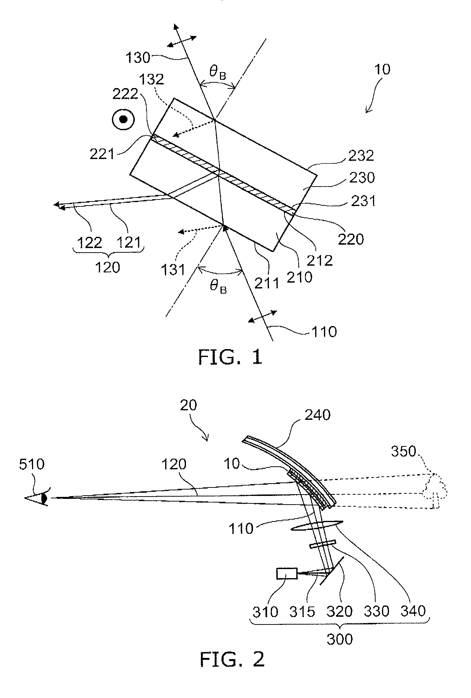
[0021]FIG. 1 is a schematic view illustrating the configuration of a head-up display optical film according to a first embodiment of the invention.

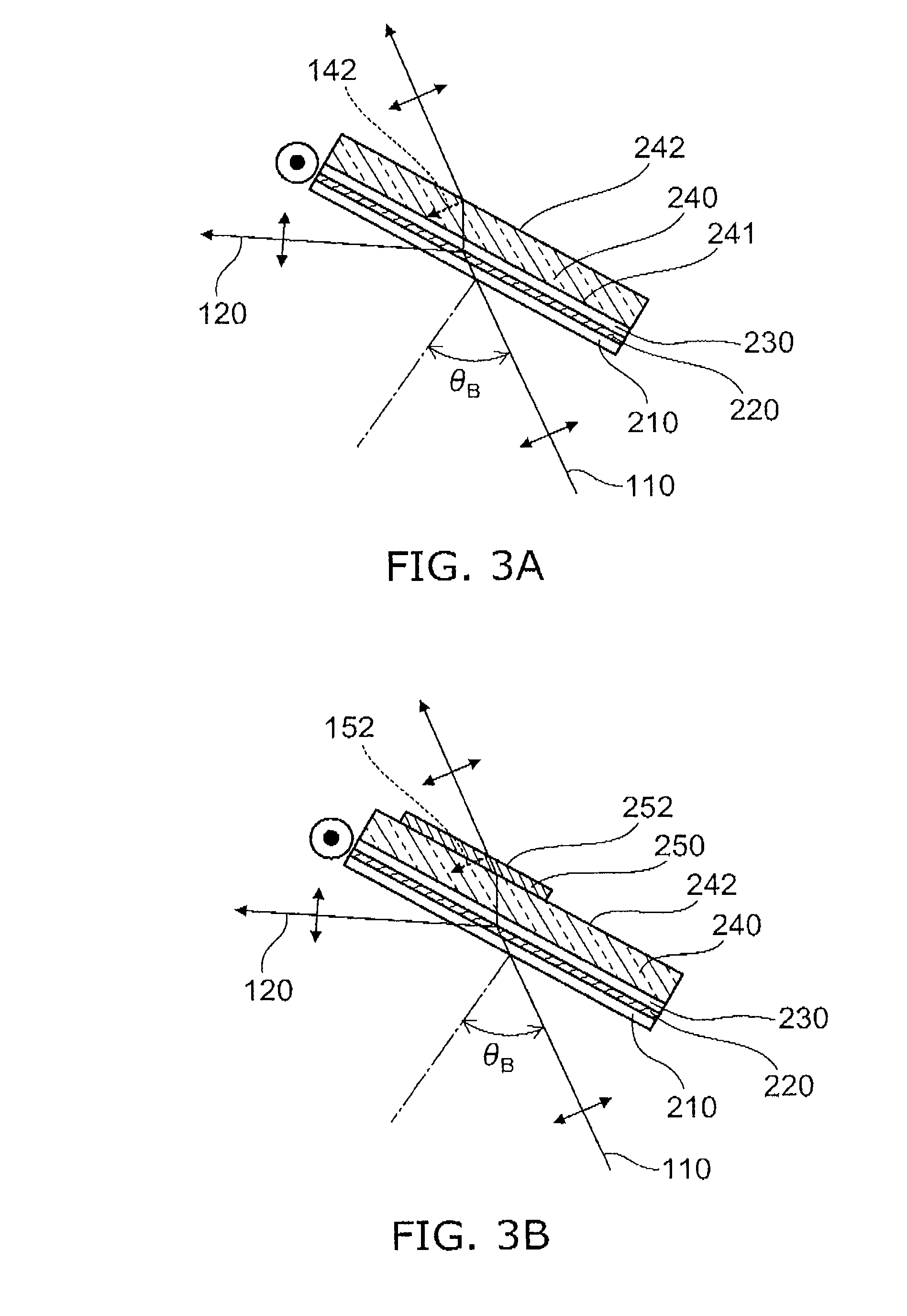
[0022]As shown in FIG. 1, the head-up display optical film 10 of the first embodiment includes a first optical layer 210 for converting the polarization plane of incident light by 90 degrees, a second optical layer 230 for converting the polarization plane of incident light by 90 degrees, and an intermediate optical layer 220 sandwiched between the first optical layer 210 and the second optical layer 230. The refractive index n2 of the intermediate optical layer 220 is designed to be different from both the refractive index n1 of the first optical layer 210 and the refractive index n3 of the second optical layer 230.

[0023]The first optical layer 210 and the second optical layer 230 can be a half-wave plate illustratively made of a stretched film of an organic resin, and accordingly serve to convert the incident light from P-polarization t...

second embodiment

[0039]Next, a head-up display according to a second embodiment of the invention is described.

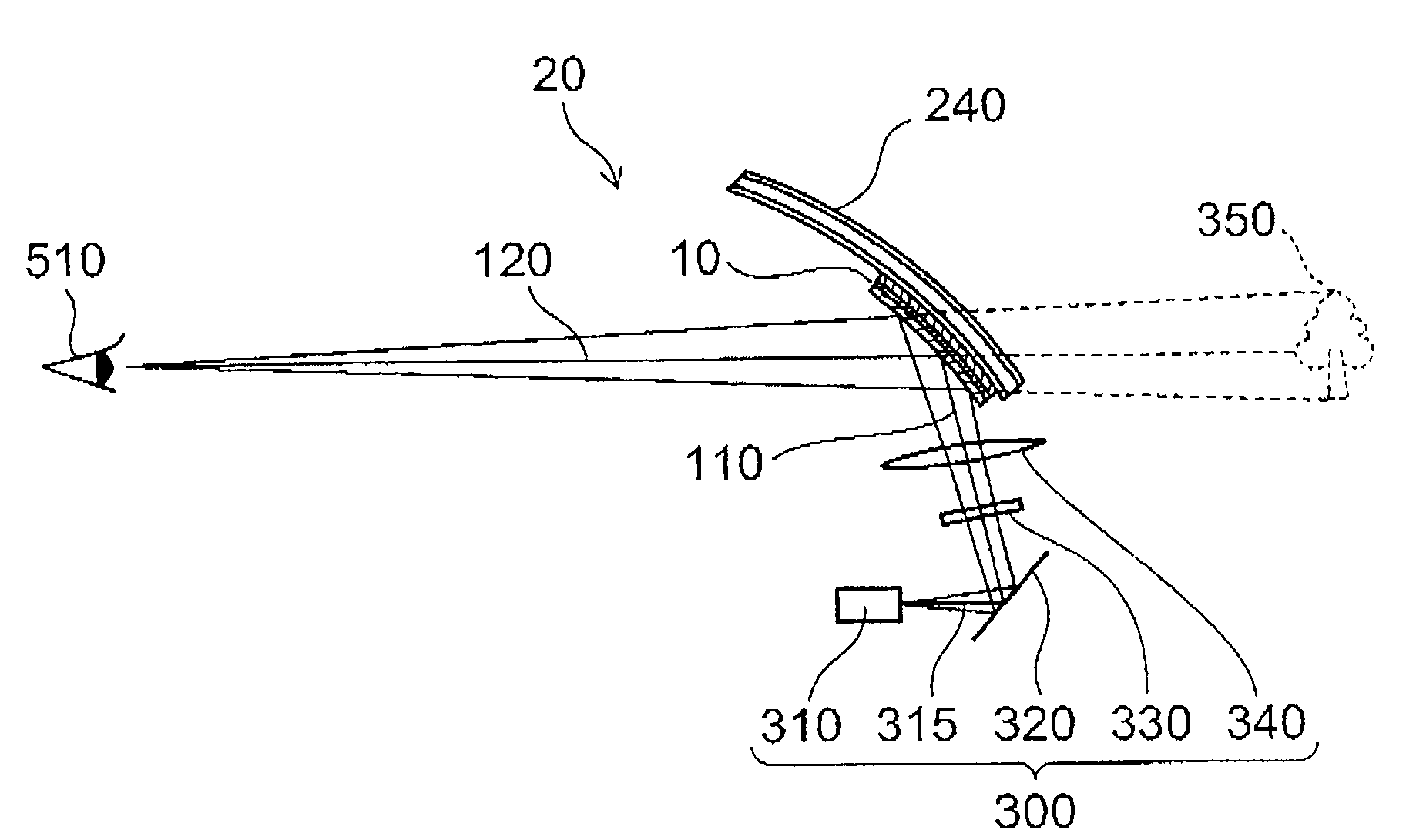
[0040]FIG. 2 is a schematic view illustrating the configuration of a head-up display according to the second embodiment of the invention.

[0041]As shown in FIG. 2, the head-up display 20 of the second embodiment includes the head-up display optical film 10 described above and a projector 300 for causing a P-polarized light beam to be incident on the optical film 10 at Brewster's angle. The light beam 315 emitted from a light source 310 is reflected by a reflector 320, then travels through a screen 330 and a lens 340, and is incident as incident light 110 on the head-up display optical film 10. Then, the incident light 110 produces reflected light 120, which reaches the viewer's eye 510. Thus, the viewer can view a virtual image 350.

[0042]In the example of FIG. 2, the distance between the light source 310 and the reflector 320 can be 100 mm, the distance between the reflector 320 and the scree...

third embodiment

[0082]In FIG. 2, the transparent plate 240 can illustratively be a car windshield. Thus, simultaneously with the image information of the background field outside the car windshield, various traffic information can be displayed and viewed on the windshield.

[0083]FIG. 9 is a schematic view illustrating a vehicle according to a third embodiment of the invention.

[0084]As shown in FIG. 9, the window, for example, in various vehicles of the third embodiment of the invention, such as a car, train, ship, helicopter, and aircraft, can be based on the transparent plate 240 to realize the head-up display of the above embodiment.

[0085]Hence, the image is visible even using a polarized sunglass that blocks S-polarized light. Reflectance at the glass outside surface can be reduced also in rainy weather, achieving good visibility with high reflectance at the display surface. Thus, a safe vehicle capable of efficient travel can be provided.

[0086]In the foregoing, the intermediate optical layer 220...


PUM


Abstract

A head-up display optical film includes: a first optical layer configured to convert the polarization plane of incident light by 90 degrees; a second optical layer configured to convert the polarization plane of incident light by 90 degrees; and an intermediate optical layer sandwiched between the first optical layer and the second optical layer and having a refractive index that is different from the refractive index of the first optical layer and from the refractive index of the second optical layer.

Description

CROSS-REFERENCE TO RELATED APPLICATIONS[0001]This application is based upon and claims the benefit of priority from the prior Japanese Patent Application No. 2007-304029, filed on Nov. 26, 2007; the entire contents of which are incorporated herein by reference.BACKGROUND OF THE INVENTION[0002]1. Field of the Invention[0003]This invention relates to a head-up display optical film, a head-up display, and a vehicle.[0004]2. Background Art[0005]The so-called head-up display (HUD) can display various traffic information on the windshield of a vehicle such as a car and an aircraft to visually present the traffic information simultaneously with the image information of the external background field. In such a head-up display, there is a 3-4% reflection at each air interface on the inside and outside of the windshield, which doubles the projected image and deteriorates visibility.[0006]To solve this, there is a method of providing a low-reflection layer on the outside of the windshield to d...

Claims


Application Information

Patent Timeline
Patent Type & Authority Applications(United States)
IPC IPC(8): G02B5/30G02B1/08G02B27/01
CPCG02B5/30G02B2027/012G02B27/0101G02B5/3083
Inventor OKADA, NAOTADAHORIUCHI, KAZUOOKUMURA, HARUHIKOSASAKI, TAKASHI
Owner KK TOSHIBA
Why Eureka
Try Eureka