

Electronic apparatus housing cover, electronic apparatus, and projector
a technology for electronic equipment and housing covers, which is applied in the field of electronic equipment housing covers, electronic equipment, and projectors, and can solve the problems of reducing the sound pressure of the sound output of the speaker device and reducing the sound quality of the speaker devi
- Summary
- Abstract
- Description
- Claims
- Application Information
AI Technical Summary
Benefits of technology
Problems solved by technology
Method used
Image

Examples
first embodiment
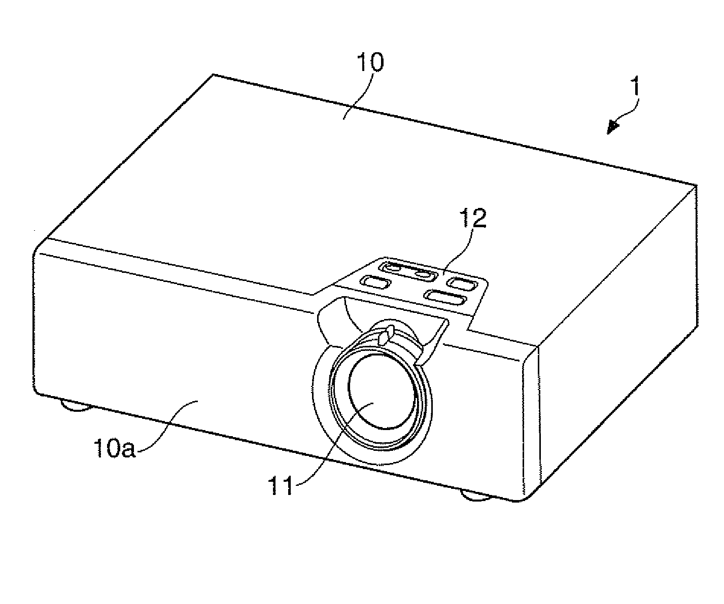
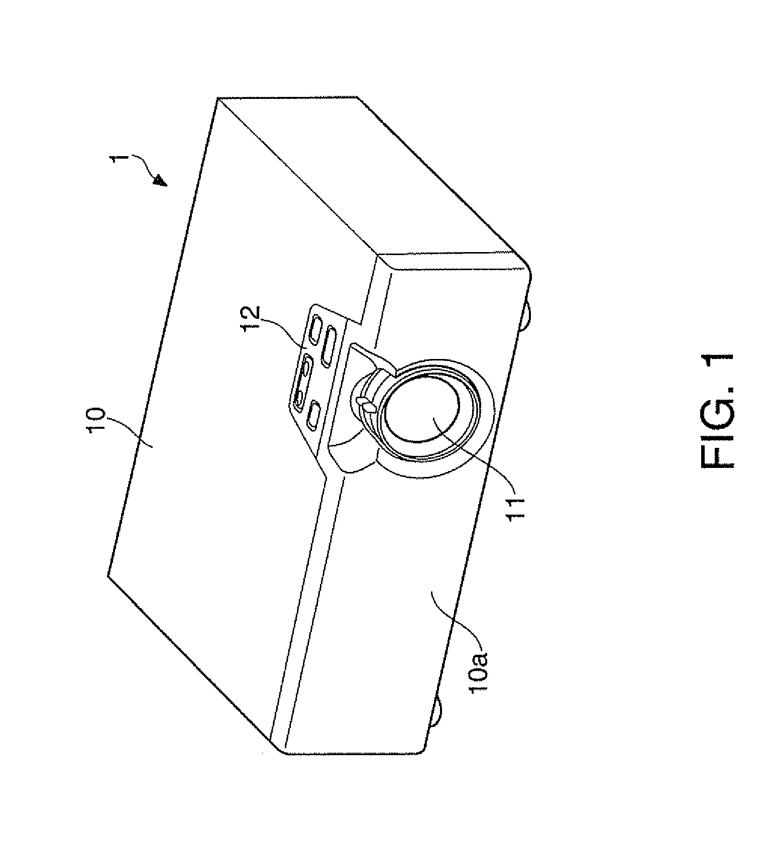
[0034]FIG. 1 is a perspective view of a projector according to a first embodiment, viewed from the front side thereof. As shown in FIG. 1, the projector 1 has a configuration in which the main body of the projector 1 is covered by a housing 10, and a front face 10a of the housing 10 is provided with a projection lens 11 as a projection optical system. Further, on the top face of the housing 10, there is disposed an input operation section 12.
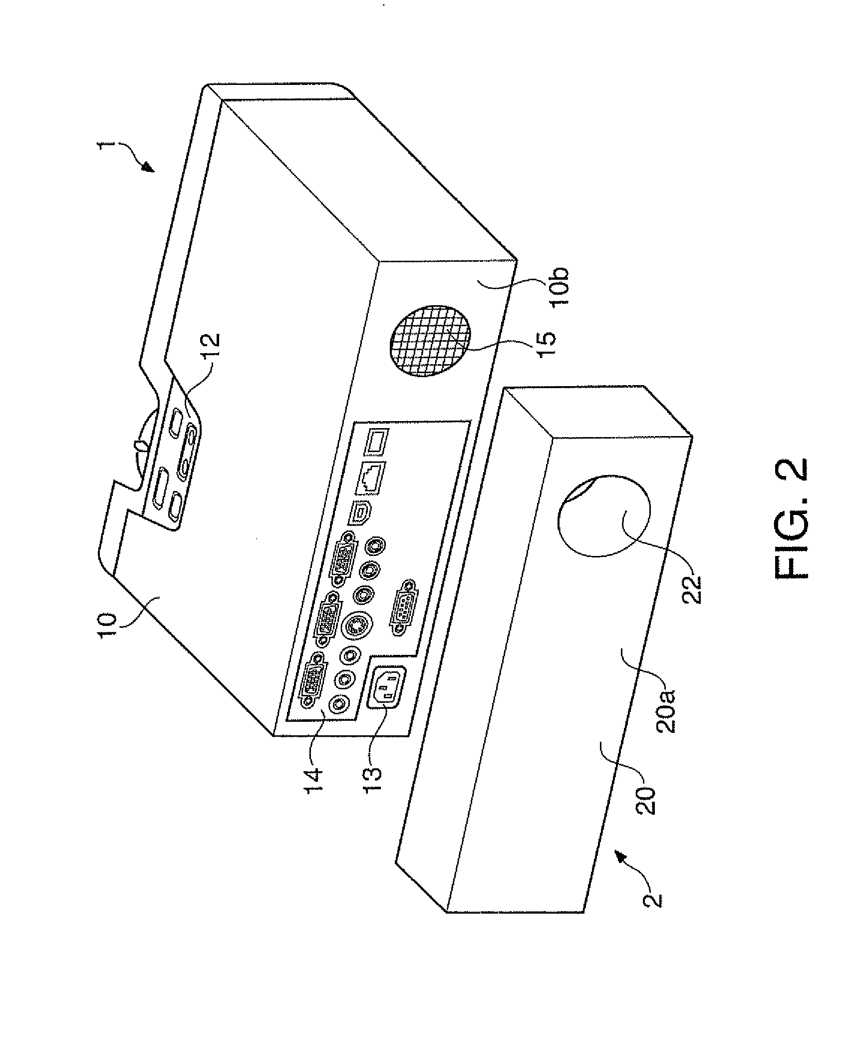
[0035]FIG. 2 is a perspective view of the projector and the projector housing cover viewed form the rear side thereof.
[0036]FIG. 3 is a perspective view of the projector housing cover viewed from the front side thereof.
[0037]In FIG. 2, the projector housing cover 2 is disposed at a position opposed to the rear face 10b of the housing 10 of the projector 1.
[0038]As shown in FIG. 2, the projector 1 is provided with a power supply terminal 13, a connection terminal group 14, a sound emission opening 15 on the rear face 10b of the housing 10.
[0039]T...
second embodiment
[0073]Hereinafter, a second embodiment will be explained.
[0074]The projector housing cover according to the present embodiment is provided with a partition plate and a port forming a Kelton type enclosure with a port, instead of the front loaded horn 22 of the projector housing cover 2 according to the first embodiment. The other constituents are the same as those of the first embodiment.
[0075]The projector housing cover will be explained with reference to FIGS. 7, 8, 9A, and 9B.
[0076]FIG. 7 is a perspective view of the projector with the projector housing cover according to the second embodiment attached thereto.
[0077]FIG. 8 is a perspective view of a projector housing cover according to the second embodiment, viewed from the front side thereof.
[0078]FIGS. 9A and 9B are cross-sectional diagrams of the projector with the projector housing cover according to the second embodiment attached thereto. FIG. 9A is the cross-sectional diagram thereof viewed from the upper side, and FIG. 9B ...
third embodiment
[0088]Hereinafter, a third embodiment will be explained.
[0089]The projector housing cover according to the present embodiment is provided with a passive radiator forming a Kelton type enclosure with a passive radiator, instead of the port 33 of the projector housing cover 3 according to the second embodiment. The other constituents are the same as those of the second embodiment.
[0090]The projector housing cover will be explained with reference to FIGS. 10, 11, 12A, and 12B.
[0091]FIG. 10 is a perspective view of the projector with the projector housing cover according to the third embodiment attached thereto.
[0092]FIG. 11 is a perspective view of a projector housing cover according to the third embodiment, viewed from the front side thereof.
[0093]FIGS. 12A and 12B are cross-sectional diagrams of the projector with the projector housing cover according to the third embodiment attached thereto. FIG. 12A is the cross-sectional diagram thereof viewed from the upper side, and FIG. 12B is ...
PUM
 Abstract
Description
Claims
Application Information