Method and systems for operating turbine engines

a technology of turbine blades and systems, applied in the direction of force/torque/work measurement apparatus, process and machine control, instruments, etc., can solve the problems of turbine blade operation at or close to the design limit, severe thermal stress on the turbine blade, and increased mechanical stress on the blade during operation

Active Publication Date: 2009-07-16
GENERAL ELECTRIC CO
View PDF2 Cites 28 Cited by
  • Summary
  • Abstract
  • Description
  • Claims
  • Application Information

AI Technical Summary

Benefits of technology

[0007]The present application thus describes a method of operating a turbine, the method including the steps of: 1) gathering thermal profile data for a blade while the turbine operates at different operating temperatures; 2) gathering operating conditions data for the turbine while the turbine operates at the different operating temperatures, including at least a rotational speed of the turbine; 3) based on the rotational speed of the turbine at the different operating temperatures, determining the mechanical stress applied to the blade; 4) given the thermal profile data for the blade and the mechanical stress applied to the blade, calculating predicted creep rate data for the blade while the turbine operates at the different operating temperatures (wherein the different operating temperatures include at least a first operating temperature and a second operating temperature); and 5) given the predicted creep rate data for the blade while the turbine operated at the first operating temperature and the predicted creep rate data for the blade while the turbine operated at the second operating temperature, determining whether operating the turbine at the first operating temperature or the second operating temperature is more economically

Problems solved by technology

Thermal stresses placed on the turbine blades associated with these conditions are severe.
In addition, the desire to design turbine blade tip shrouds of greater surface area has added addition weight to the end of the turbine blade, which has further increased the mechanical stresses applied to the blades during operation.
When these mechanical stresses are coupled with the severe thermal stresses, the result is that turbine blades operate at or close to the design limits of the material.
Similarly, compressor blades undergo a high level of mechanical stress due to the forces applied via the rotational speed of the compressor.
As a result compressor blades also may undergo the slow deformation associated with metal creep.
As a result, the turbine blade and compressor blade failure mode of primary concern in a turbine is metal creep, and particularly radial metal creep (i.e., elongation of the turbine or compressor blade).
If lef

Method used


Image

  • Method and systems for operating turbine engines
  • Method and systems for operating turbine engines
  • Method and systems for operating turbine engines

Examples


Embodiment Construction

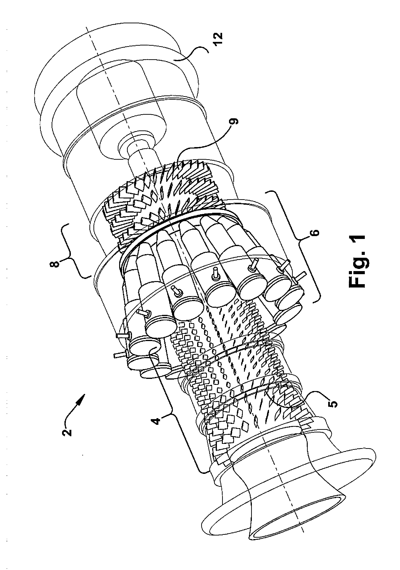
[0018]A technique has been developed to measure accurately, reliable, and at a relatively low cost the deformation of turbine blades in real time, i.e., as the gas turbine is operating. Referring now to FIG. 1, a typical gas turbine 2 is illustrated in which exemplary embodiments of the present invention may be used. While FIG. 1 depicts a gas turbine, it is understood that the present invention also may be used in steam turbines also. As shown, the gas turbine 2 may include a compressor 4, which may include several stages of compressor blades 5, which compresses a working fluid, i.e., air. The gas turbine 2 may include a combustor 6 that combusts a fuel with the compressed air. The gas turbine 2 further may include a turbine 8 that includes several stages of airfoils or turbine blades 9, which convert the energy from the expanding hot gases into rotational mechanical energy. As used herein, the term “blades” will be used to refer to either compressor blades or turbine blades. The t...


PUM


Abstract

A method of operating a turbine, the method including the steps of: 1) gathering measured creep data for a blade while the turbine operates at different operating temperatures, the measured creep data comprising at least a measured creep rate for the blade (wherein the different operating temperatures include at least a first operating temperature and a second operating temperature); and 2) given the measured creep data for the blade while the turbine operated at the first operating temperature and the measured creep data for the blade while the turbine operated at the second operating temperature, determining whether operating the turbine at the first operating temperature or the second operating temperature is more economically efficient.

Description

BACKGROUND OF THE INVENTION[0001]This present application relates generally to methods and systems for determining turbine blade deformation. More specifically, but not by way of limitation, the present application relates to methods and systems for measuring turbine blade deformation while the turbine is operating.[0002]The turbine blades of industrial gas turbines, steam turbines, and aircraft engines operate in a high temperature environment, where the temperatures regularly reach between 600° C. and 1500° C. Moreover, the general trend is to increase the turbine operating temperatures to increase output and engine efficiencies. Thermal stresses placed on the turbine blades associated with these conditions are severe.[0003]In general, turbine blades undergo high level of mechanical stress due to the forces applied via the rotational speed of the turbine. These stresses have been driven to even higher levels in an effort to accommodate turbine blade design that include higher annu...

Claims


Application Information

Patent Timeline
IPC IPC(8): F02C9/00F04D27/00G01M15/14
CPCG01M15/14F05B2260/80F05D2260/80F05D2270/804
Inventor DRAPER, SAM D.HOYTE, SCOTT M.GEBHARDT, ERICBAUKNIGHT, ERIN K.
Owner GENERAL ELECTRIC CO
Why Eureka
Try Eureka