
Concrete form alignment tool and method of use

a technology of concrete form and tool, which is applied in the direction of form/shuttering/falseworks, building material handling, and shaping building parts, etc., can solve the problem of inconvenient use and large columns that are required for correct positioning

Active Publication Date: 2009-07-16
STEVENS GEORGE C
View PDF33 Cites 4 Cited by
  • Summary
  • Abstract
  • Description
  • Claims
  • Application Information

AI Technical Summary

Benefits of technology

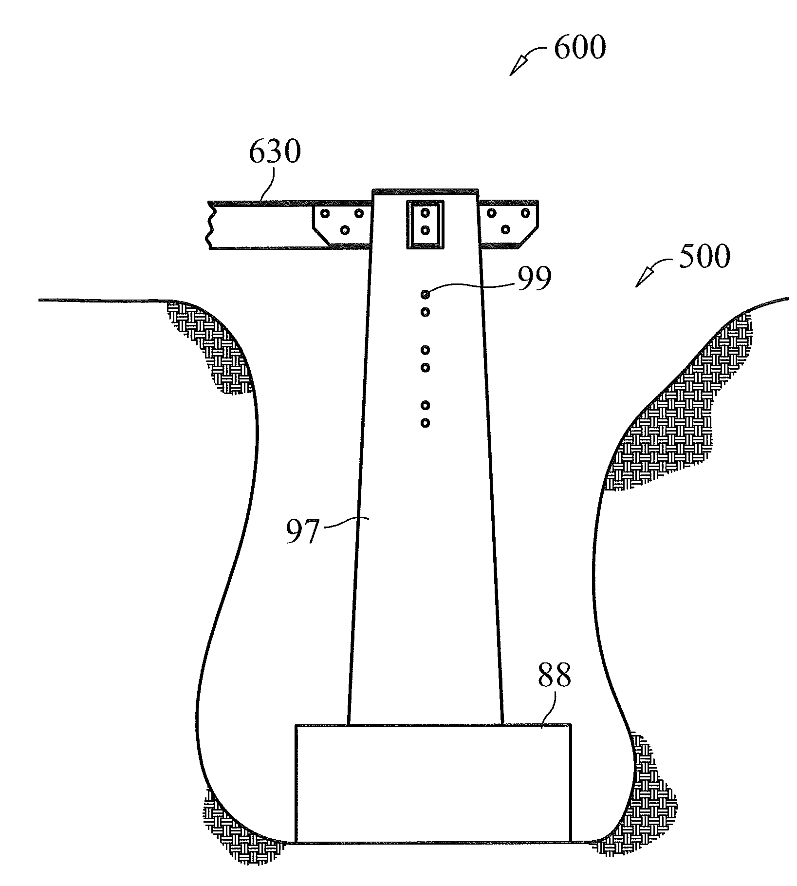
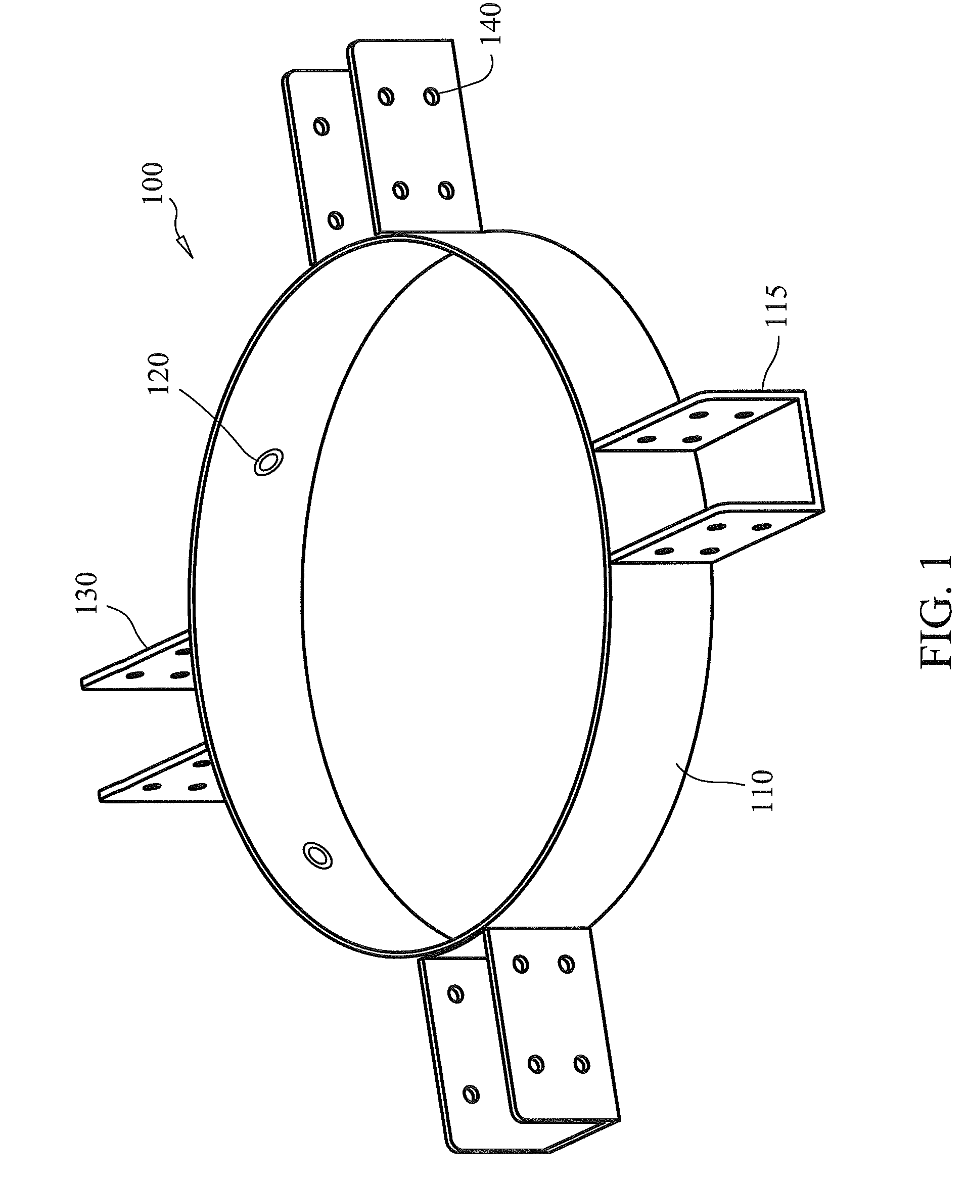
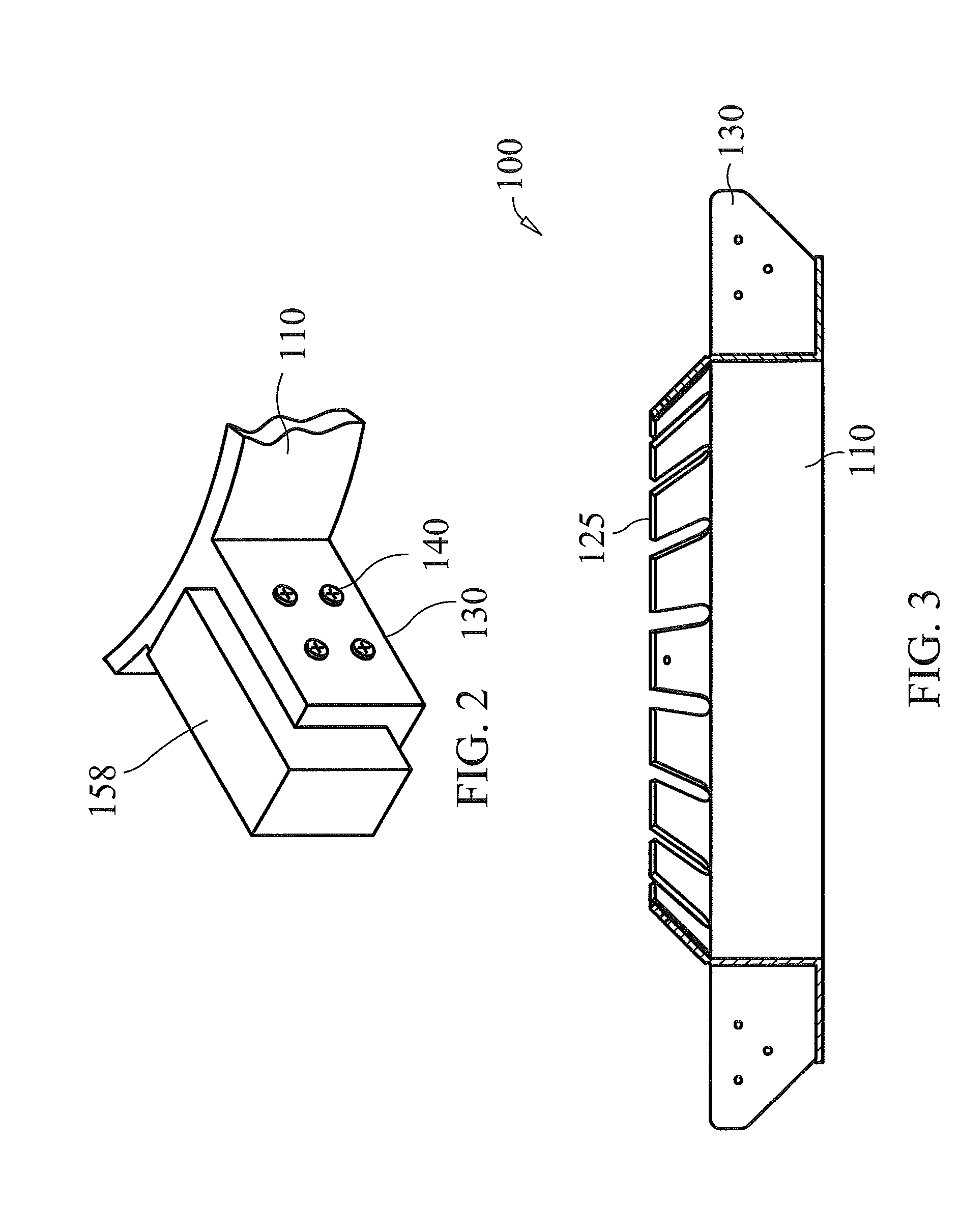
"The invention is an aligning apparatus for concrete column forms. It includes at least two platforms that engage the form, a securing device to fix and center the platforms, attachment brackets that are affixed on the platforms at a predetermined angle, and a connector mechanism in the attachment brackets. The attachment brackets can be aligned with one another to facilitate the connection of a brace. The invention also includes a plurality of rings that surround the form and are fixed beneath the top using a biasing device. The rings can be rotated and stacked on top of each other, and attachment brackets are affixed on each ring at a predetermined angle from each other. The invention also includes a method for aligning the apparatus around support columns and connecting it with a brace at the proper angle and distance between the aligning apparatuses. The technical effects of the invention include improved accuracy and efficiency in the alignment process for concrete column forms."

Problems solved by technology

However, plumb lines can easily move or be repositioned because the lines may collapse or move when not under tension and therefore may shift or worse the top may tilt and while the base is properly positioned the top of the concrete column is incorrectly positioned to receive the leg of the structure.
In extreme cases the cured column needs to be excavated and re-poured or in certain areas incorrect positioning has required larger sized columns than required just for top alignment purposes.

Method used


Image

  • Concrete form alignment tool and method of use
  • Concrete form alignment tool and method of use
  • Concrete form alignment tool and method of use

Examples


Embodiment Construction

[0032]Although certain preferred embodiments of the present invention will be shown and described in detail, it should be understood that various changes and modifications may be made without departing from the scope of the appended claims. The scope of the present invention will in no way be limited to the number of constituting components, the materials thereof, the shapes thereof, the relative arrangement thereof, etc., and are disclosed simply as an example of an embodiment. The features and advantages of the present invention are illustrated in detail in the accompanying drawings, wherein like reference numerals refer to like elements throughout the drawings.

[0033]As a preface to the detailed description, it should be noted that, as used in this specification and the appended claims, the singular forms “a”, “an” and “the” include plural referents, unless the context clearly dictates otherwise.

[0034]The instant invention assists with the building of decks, sheds, etc. by the ave...


PUM


Abstract

A concrete column form aligning apparatus is useful for homeowners building decks, sheds or other structures or commercial builders making bridges, parking garages or other structures having column forms. The aligning apparatus comprises a plurality of platforms configured to engage a circumference of the concrete column form each having a securing device to fix and center each platform around the circumference of the concrete column form. Each of the apparatuses have at least one attachment bracket affixed at a predetermined angle, where the attachment brackets on each form linearly aligned at the proper angle with respect to the other attachment bracket on the other platform. A connector mechanism may be secured in the attachment bracket be using joining pieces at a designated length that secures and aligns the forms at the proper position.

Description

CROSS REFERENCE TO RELATED APPLICATIONS[0001]NoneBACKGROUND OF THE INVENTION[0002]The building of decks, sheds, etc. by the average homeowner or in a commercial construction applications such as bridge work, parking garages, and all industrial construction as well, columns made of poured concrete both above and below grade are typically aligned using plumb lines and supported with braces. Modern construction codes also may require a concrete footing at the required depth below the frost line to support the legs or base of the structure. Typically forms were set up with plumb lines and dug then braced to the ground and backfilled based upon the measurements of the lines. However, plumb lines can easily move or be repositioned because the lines may collapse or move when not under tension and therefore may shift or worse the top may tilt and while the base is properly positioned the top of the concrete column is incorrectly positioned to receive the leg of the structure. In extreme cas...

Claims


Application Information

Patent Timeline
Patent Type & Authority Applications(United States)
IPC IPC(8): E04G13/02E04B1/19
CPCE04G17/14E04G13/02
Inventor STEVENS, GEORGE C.
Owner STEVENS GEORGE C
Learn More