Desktop Stapler

a stapler and desk technology, applied in the field of desk staplers, can solve the problems of frame installation on the base b>10/b> undetachable and not convenient for users

Inactive Publication Date: 2009-07-23
APEX MFG
View PDF16 Cites 22 Cited by
  • Summary
  • Abstract
  • Description
  • Claims
  • Application Information

AI Technical Summary

Problems solved by technology

However, the frame is installed on the base 1

Method used


Image

  • Desktop Stapler
  • Desktop Stapler
  • Desktop Stapler

Examples


first embodiment

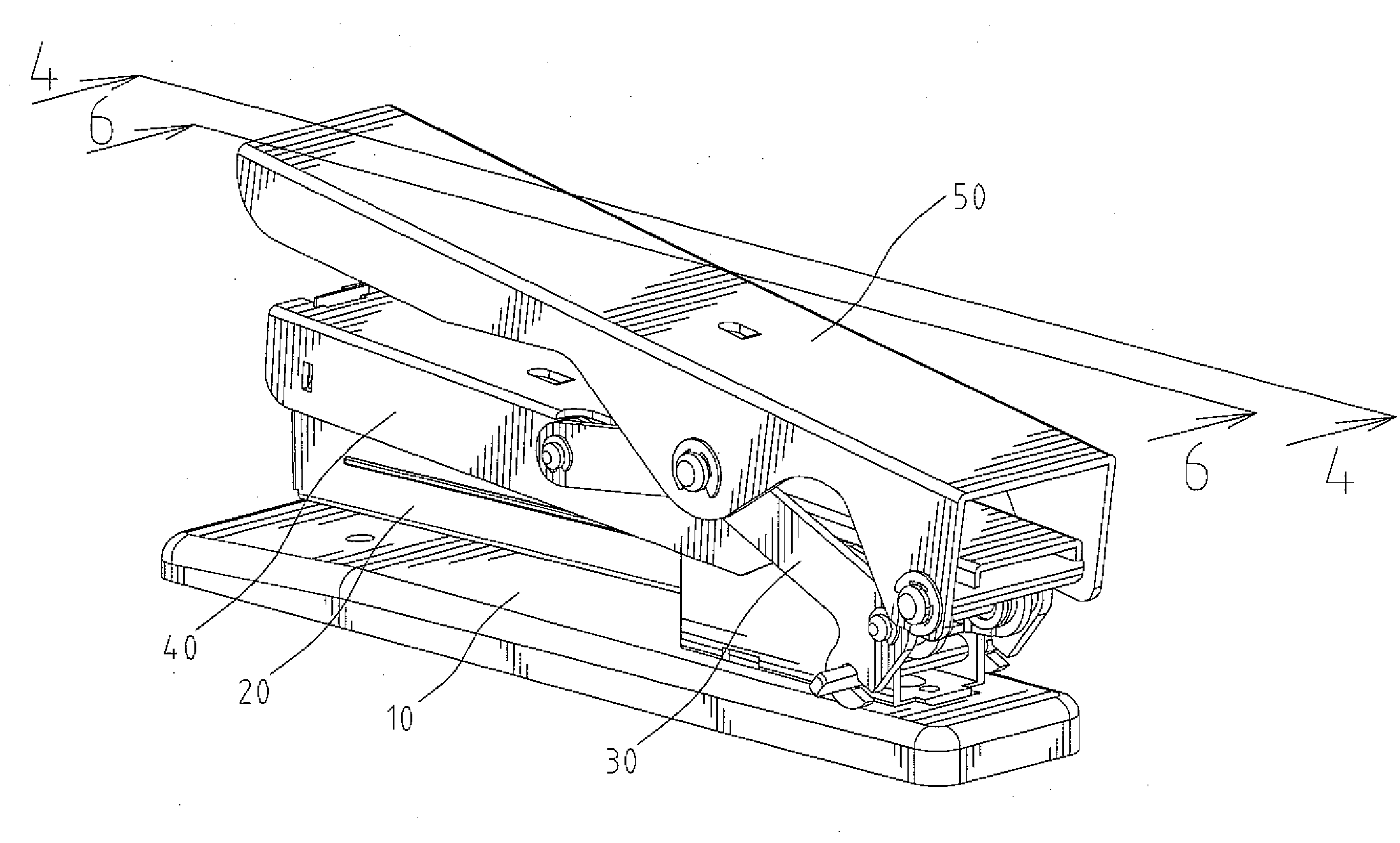
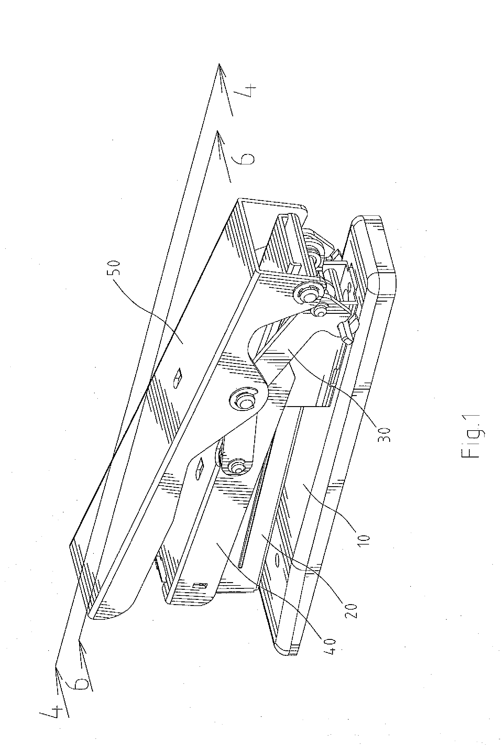
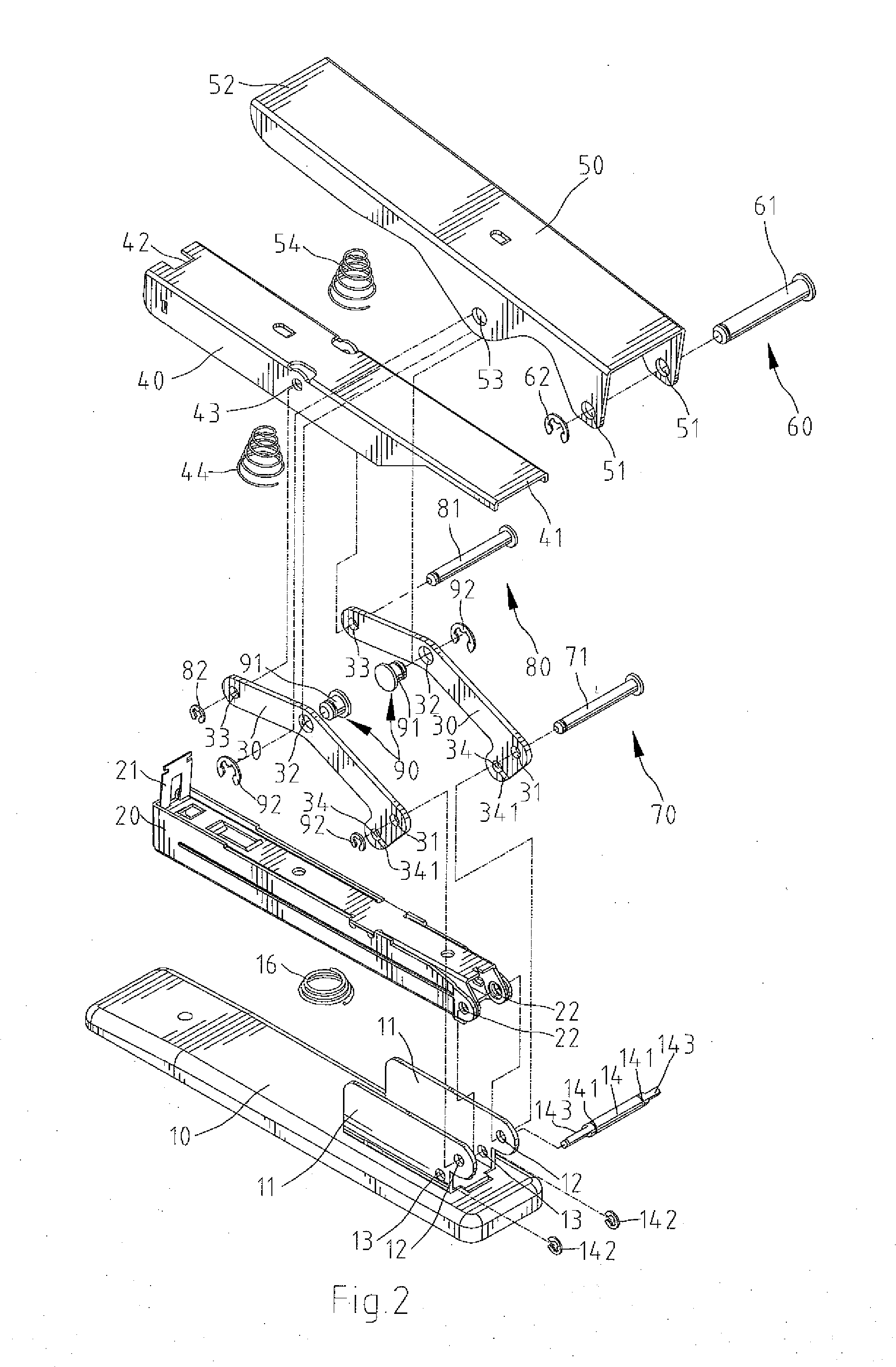
[0019]Referring to FIGS. 1 and 2, a desktop stapler in accordance with a first embodiment in the present invention includes a base member 10, a magazine 20 pivotally installed to the base member 10, two linkage devices 30 located on the base member 10 and pivotally connected with the magazine 20 respectively, a press member 40 pivotally connected with the linkage devices 30, a guide member 50 mounted on the press member 40 and pivotally connected with the linkage devices 30, and a plurality of coupler units 60, 70, 8090. The coupler unit 60, 70, 8090 respectively include shafts 61, 71, 81, 91 and C-shaped fasteners 62, 72, 82, 92. An end of each shaft 61, 71, 81, 91 forms a groove for receiving the fastener 62, 72, 82, 92.

[0020]The base member 10 includes two blade portions 11 disposed on the rear thereof, a pivot hole 12 and a fixed hole 13 respectively formed on the rear of each blade portion 11 and adjacent to each other, a restricting unit 14 inserting through the fixed holes 13...

second embodiment

[0035]Consequently, the stapler in accordance with the second embodiment in the present invention can provide to save users force about to 88.636%.


PUM


Abstract

A desktop stapler comprises a base member including a restricting unit; a magazine including a plunger disposed on the head thereof; two linkage devices, with each linkage device including a first hole, a third hole, a second hole formed on a bent between the first and third holes, and a pivot hole, with each pivot hole adapted to connect with the base member via the restricting unit; a press member including a press portion defined on the bottom of an end thereof a grip portion defined on another end thereof and connecting to the plunger of the magazine, and two pivot holes formed on two sidewalls thereof and connect to the third holes of the linkage devices respectively via a coupler unit; a guide member including a first end that is inserted via a coupler unit, a second end defining a press end, and two second pivot holes formed on two sidewalls thereof and opposite to each other.

Description

BACKGROUND OF THE INVENTION[0001]1. Field of the Invention[0002]The present invention relates to a desktop stapler.[0003]2. Description of the Related Art[0004]A conventional stapler is improved for saving force to eject staples, as shown in reference Taiwan Patent NO M299629. Meanwhile, the stapler includes a linkage unit 40 having a first linkage 41 and a second linkage 42. The rear end of the first linkage 41 pivotally connects to the base 11; the head of the second linkage 42 is pivotally disposed to the press member 31 and the rear of the second linkage 42 pivotally connects to the first linkage 41. The advantage of the stapler in this reference is that the force of exerting to eject staples can be reduced via the specific arms of force according as the specific positions where the linkage unit 40 couples to parts of the stapler. Therefore, it can save users force for ejecting staples to 55%.[0005]Furthermore, another conventional stapler is improved for saving force to eject s...

Claims


Application Information

Patent Timeline
IPC IPC(8): B25C5/11B25C5/02
CPCB25C5/11B25C5/0221
Inventor TSAI, ERIC
Owner APEX MFG
Why Eureka
Try Eureka