Method of Manufacturing Toner Carrier Roller, Developer Apparatus, and Image Forming Apparatus

a technology of toner carrier roller and developer, which is applied in the direction of electrographic process apparatus, metal-working apparatus, instruments, etc., can solve the problems of toner leakage, toner adhesion to the surface of the seal member, and toner leakage, so as to reduce the adhesion of toner, reduce the effect of differences, and reduce the effect of scraping

Inactive Publication Date: 2009-07-23
SEIKO EPSON CORP
View PDF4 Cites 11 Cited by
  • Summary
  • Abstract
  • Description
  • Claims
  • Application Information

AI Technical Summary

Benefits of technology

[0016]According to a third aspect of the invention, there is provided a developer apparatus, comprising: a housing that stores toner inside; a toner carrier roller that is shaped approximately like a cylinder, is mounted to the housing rotatably about a rotational axis, rotates while carrying toner on a surface thereof to convey the toner to outside the housing, and is provided, on the surface thereof, with a plurality of convex sections which are regularly arranged and a concave section which surrounds the convex sections, the convex sections including top surfaces that coincide with a part of a cylindrical surface of a single cylinder; and a seal member that is arranged in abutting contact with the surface of the toner carrier roller moving from the outside the housing toward the inside the housing to prevent toner leakage from the inside the housing, wherein out of surrounding area of the top surface of each of the convex sections, a portion located at front-most in a moving direction associated with rotation of the toner carrier roller is a leading portion of the convex section, and a maximum value of gaps in an axial direction, which is parallel to the rotational axis of the toner carrier roller, between the trajectories which the leading portions of the convex sections follow while the toner carrier roller rotates one round is smaller than a volume average particle diameter of the toner.
[0017]In this structure according to this aspect of the invention, the leading portions of the respective convex sections scrape off toner on the seal member, and toner adhering to the surface of the seal member located on the trajectories of the leading portions gets scraped off due to this function. Since toner in an area not included in the trajectory of any leading portion within the surface of the toner carrier roller is not exposed to scraping, it is ideal that such an area is reduced as much as possible. According to the invention, the gaps between the trajectories are, even when the largest, smaller than a volume average particle diameter of the toner. Hence, it is possible to scrape off from the surface of the toner carrier roller without fail such toner whose particle diameters are equal to or larger than at least an average particle diameter. That is, it is possible according to this aspect of the invention to suppress adhesion of toner to the seal member and prevent a problem such as toner leakage and filming attributable to adhesion of toner to the seal member.
[0018]According to a fourth aspect of the invention, there is provided a developer apparatus, comprising: a housing that stores toner inside; a toner carrier roller that is shaped approximately like a cylinder, is mounted to the housing rotatably about a rotational axis, rotates while carrying toner on a surface thereof to convey the toner to outside the housing, and is provided, on the surface thereof, with a plurality of convex sections which are regularly arranged and a concave section which surrounds the convex sections, the convex sections including top surfaces that coincide with a part of a cylindrical surface of a single cylinder and have apexes which project most toward the front side in a moving direction of the surface of the toner carrier roller; and a seal member that is arranged in abutting contact with the surface of the toner carrier roller moving from the outside the housing toward the inside the housing to prevent toner leakage from the inside the housing, wherein each line that connects the apexes of two convex sections among adjacent convex sections whose positions are least different from each other in an axial direction, which is parallel to the rotational axis of the toner carrier roller, over a shortest distance along the cylindrical surface, partially forms a single helix on the cylindrical surface.
[0019]In this structure according to this aspect of the invention, the apexes of all convex sections in the surface of the toner carrier roller are located on the same helix on the cylindrical surface. Hence, the positions of the apexes of the convex sections abutting on the seal member shift by a very small distance as the toner carrier roller rotates, and return back again to their initial abutting positions when the toner carrier roller has just rotated once. In this manner, it is possible to minimize differences between the axial-direction positions of apexes which are adjacent to each other in the moving direction of the surface of the toner carrier roller, and hence, ensure a uniform effect of scraping off toner which is on the seal member in the entire axial-direction region. It is thus possible to scrape off without fail particles having small particle diameters as well while securing a uniform scraping effect in the axial direction. For this reason, it is possible according to this aspect of the invention to suppress adhesion of toner to the seal member and prevent a problem such as toner leakage and filming attributable to adhesion of toner to the seal member.
[0020]According to a fifth aspect of the invention, there is provided an image forming apparatus, comprising: a latent image carrier that carries an electrostatic latent image; a housing that stores toner inside; a toner carrier roller that is shaped approximately like a cylinder, is mounted to the housing rotatably about a rotational axis, rotates while carrying toner on a surface thereof to convey the toner to an opposed position facing the latent image carrier, and is provided, on the surface thereof, with a plurality of convex sections which are regularly arranged and a concave section which surrounds the convex sections, the convex sections including top surfaces that coincide with a part of a cylindrical surface of a single cylinder; and a seal member that is arranged in abutting contact with the surface of the toner carrier roller moving from the outside the housing toward the inside the housing to prevent toner leakage from the inside the housing, wherein out of surrounding area of the top surface of each of the convex sections, a portion located at front-most in a moving direction associated with rotation of the toner carrier roller is a leading portion of the convex section, and a maximum value of gaps in an axial direction, which is parallel to the rotational axis of the toner carrier roller, between the trajectories which the leading portions of the convex sections follow while the toner carrier roller rotates one round is smaller than a volume average particle diameter of the toner.
[0021]Using this structure according to this aspect of the invention, just like the developer apparatus described above, it is possible to suppress adhesion of toner to the seal member and prevent a problem such as toner leakage and filming attributable to adhesion of toner to the seal member.

Problems solved by technology

However, since the seal member is pressed into contact with the developing roller having the toner adhering to the surface thereof it is unavoidable that the toner adheres to the surface of the seal member.
Such adhesion of the toner to the seal member could become a cause of toner leakage resulting from a seal defect or filming resulting from the adhesion of the fixed toner to the developing roller surface.
Thus, it is thought that toner leakage, filming or the like is likely to be induced by such local toner adhesion.

Method used


Image

  • Method of Manufacturing Toner Carrier Roller, Developer Apparatus, and Image Forming Apparatus
  • Method of Manufacturing Toner Carrier Roller, Developer Apparatus, and Image Forming Apparatus
  • Method of Manufacturing Toner Carrier Roller, Developer Apparatus, and Image Forming Apparatus

Examples


Embodiment Construction

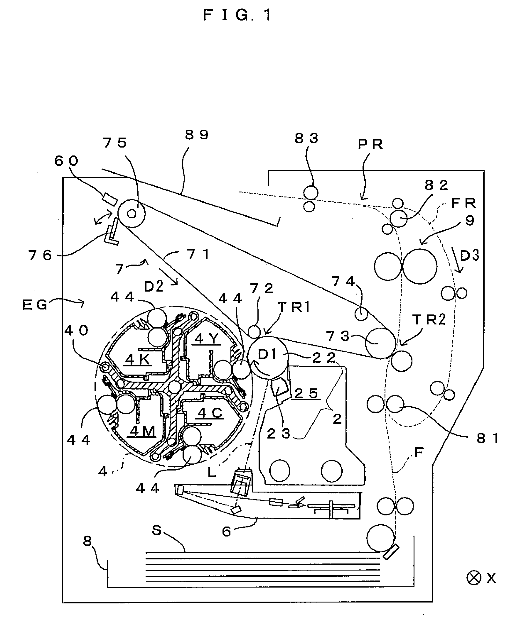
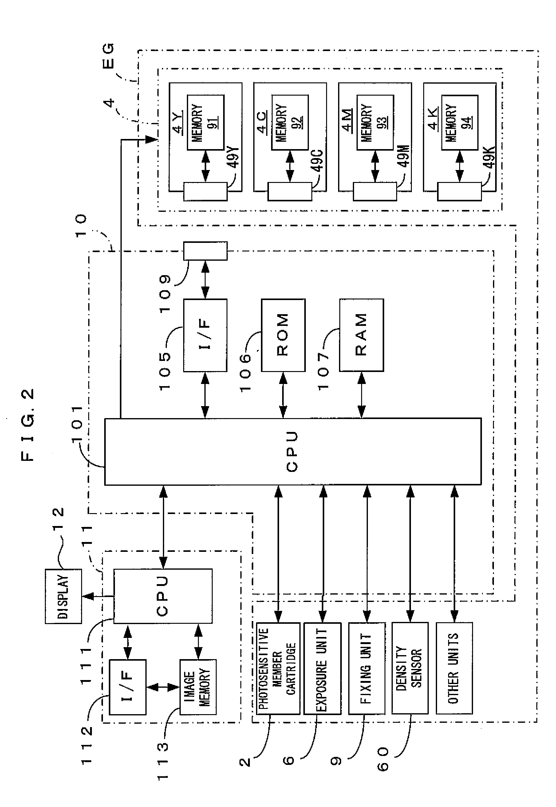
[0037]FIG. 1 is a diagram showing an embodiment of an image forming apparatus according to the invention. FIG. 2 is a block diagram of an electric structure of the image forming apparatus which is shown in FIG. 1. This apparatus is an image forming apparatus which overlays toner in four colors of yellow (Y), cyan (C), magenta (M) and black (K) one atop the other and accordingly forms a full-color image, or forms a monochromatic image using only black toner (K). In the image forming apparatus, when an image signal is fed to a main controller 11 from an external apparatus such as a host computer, a CPU 101 provided in an engine controller 10 controls respective portions of an engine part EG in accordance with an instruction received from the main controller 11 to perform a predetermined image forming operation, and accordingly, an image which corresponds to the image signal is formed on a sheet S.

[0038]In the engine part EG, a photosensitive member 22 is disposed so that the photosens...


PUM

PropertyMeasurementUnit
frequencyaaaaaaaaaa
tilt anglesaaaaaaaaaa

Abstract

A method of manufacturing a toner carrier roller that is shaped like a cylinder on an outer circumferential surface of which concave and convex sections for carrying toner are provided, includes: preparing a roller base member which is shaped like a cylinder; forming helix-like first grooves on the outer circumferential surface of the roller base member; and forming helix-like second grooves, which cross the first grooves, on the outer circumferential surface of the roller base member, wherein a pitch ratio of the first grooves and the second grooves is a non-integer ratio.

Description

CROSS REFERENCE TO RELATED APPLICATION[0001]The disclosure of Japanese Patent Application No. 2008-12148 filed on Jan. 23, 2008 including specification, drawings and claims is incorporated herein by reference in its entirety.BACKGROUND[0002]1. Technical Field[0003]The invention relates to a method of manufacturing a toner carrier roller whose surface includes concaves and convexes which are regularly formed, a developer apparatus and an image forming apparatus which use the toner carrier roller.[0004]2. Related Art[0005]In techniques for developing an electrostatic latent image carried on an image carrier with toner, an apparatus is widely used which includes a toner carrier roller which is shaped approximately like a cylinder, carries toner on a surface thereof, and is arranged opposed facing the image carrier. For the purpose of improving the characteristics of toner carried on the surface of such a toner carrier roller, the applicant of the present application has earlier disclos...

Claims


Application Information

Patent Timeline
Patent Type & Authority Applications(United States)
IPC IPC(8): G03G15/08B21D53/00
CPCY10T29/49544G03G15/0818
Inventor ARUGA, TOMOHIROMAEDA, MASAHIRO
Owner SEIKO EPSON CORP
Why Eureka
Try Eureka