Universal fastener

Inactive Publication Date: 2009-07-23
ILLINOIS TOOL WORKS INC
View PDF16 Cites 21 Cited by
  • Summary
  • Abstract
  • Description
  • Claims
  • Application Information

AI Technical Summary

Benefits of technology

[0008]The foregoing and other objectives are achieved in accordance with the teachings and principles of the present invention through the provision of a new and improved fastener which comprises a threaded shank portion, and a first large half-cone structure which comprises a radially inner flat or planar section, a radially outer conical section, and a pointed tip portion, defined upon the forward end of the fastener as a result of the geometrical intersection of the radially inner flat or planar section and the radially outer conical section of the first large half-cone structure, so as to readily, easily, and quickly commence or enable insertion of the fastener into a wood or cinder block or concrete substrate. A second small half-cone structure may be disposed upon and be integral with the radially inner flat or planar section of the first large half-cone structure at a position located axially rearward of the pointed tip portion. Threads are provided upon a forward shank portion of the fastener and terminate immediately upstream of or adjacent to the first large half-cone structure or immediately upstream of or adjacent to the second small half-cone structure when the second small half-cone structure is disposed upon and integral with the inner flat or planar section of the first large half-cone structure.
[0009]By providing this new and improved tip portion upon the fastener, comprising only a single first large half-cone structure, or comprising a second small half-cone structure integrally disposed upon the radially inner flat or planar section of the first large half-cone structure, an enlarged clearance space or path is effectively defined upon the forward end portion of the fastener which permits debris, dust, and the like, generated during the threaded insertion or tapping process of the screw fastener into a cinder block or concrete substrate, to be readily and quickly eliminated or discharged. In this manner, the debris, dust, or the like, does not accumulate within the pre-drilled bore formed within the cinder block or concrete substrate, and therefore the insertion torque that needs to be exerted upon the fastener, when the fastener is to be inserted into the cinder block or concrete substrate, is effectively reduced.
[0010]Alternatively, when the new and improved fastener is inserted into a wood substrate, the absence of a second large half-cone structure disposed diametrically opposite the first large half-cone structure, or the provision of the second small half-cone structure upon the first large half-cone structure, effectively reduces the amount of surface area of the forward end portion of the fastener that will initially be engaged with the wood substrate so as to likewise facilitate the insertion of the fastener into the wood substrate with less force or torque. Still further, the provision of the pointed tip portion, defined upon the forward end of the fastener as a result of the geometrical intersection of the radially inner flat or planar section and the radially outer conical section of the first large half-cone structure, together with the radially inner flat or planar section of the first large half-cone structure, or together with the second small half-cone structure, permits the fastener to be readily and easily inserted into the concrete or cinder block or wood substrate whereupon the first thread of the fastener, disposed upon the threaded shank portion of the fastener and disposed immediately adjacent to or upstream of the first large half-cone structure, can effectively begin to threadedly engage the concrete or cinder block or wood substrate.

Problems solved by technology

While this type of fastener 210 is generally satisfactory, it does have some operational flaws or drawbacks.
In addition, it is difficult and tedious to insert the fastener into concrete substrates in view of the fact that the full or complete conically configured, pointed gimlet tip portion 214 of the fastener 210 does not provide a large enough or adequate clearance space or path at the forwardmost end portion of the fastener, when a hole 232 is predrilled within the cinder block or concrete 202.
The generation of such substantially increased insertion torque not only results in the insertion process being more tedious and difficult for operator personnel to achieve, but in addition, substantially increases the time it takes to insert the fastener 210 into the cinder block or concrete structure 202.
Still further, the conventional fastener 210 is also difficult and tedious when the same is to be inserted into wood substrates.
Still yet further, since the fastener 210 is not optimally designed for use within cinder block or concrete substrates, operational field personnel must use different fasteners dependent upon whether or not it is desired to insert a fastener into a particular one of the two different substrates, that is, either a wood substrate or cinder block or concrete substrate.

Method used


Image

  • Universal fastener
  • Universal fastener
  • Universal fastener

Examples


Embodiment Construction

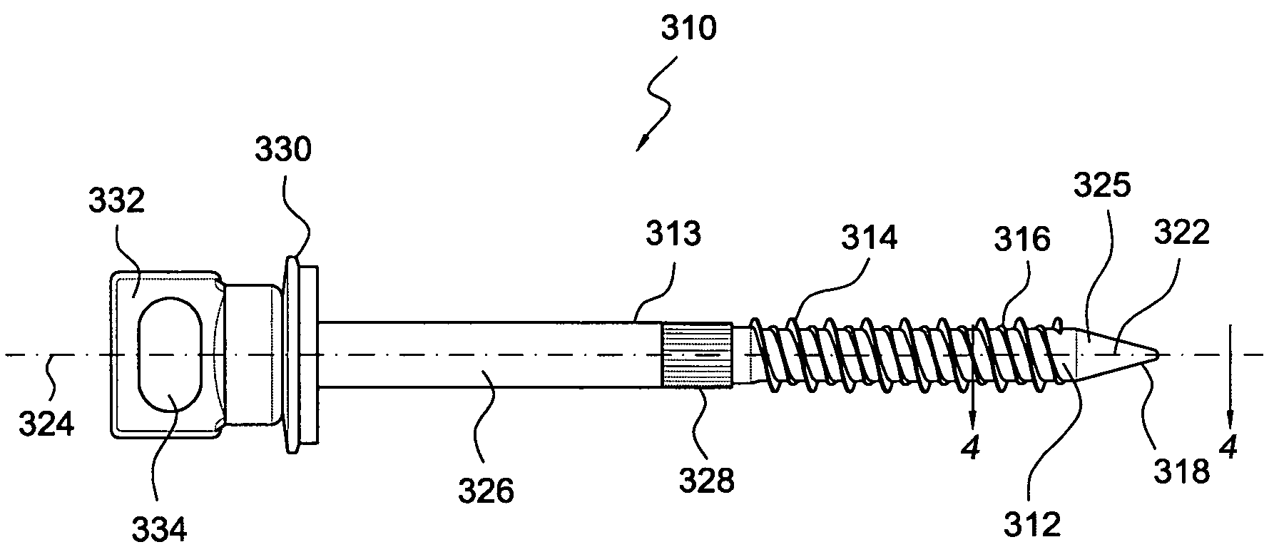
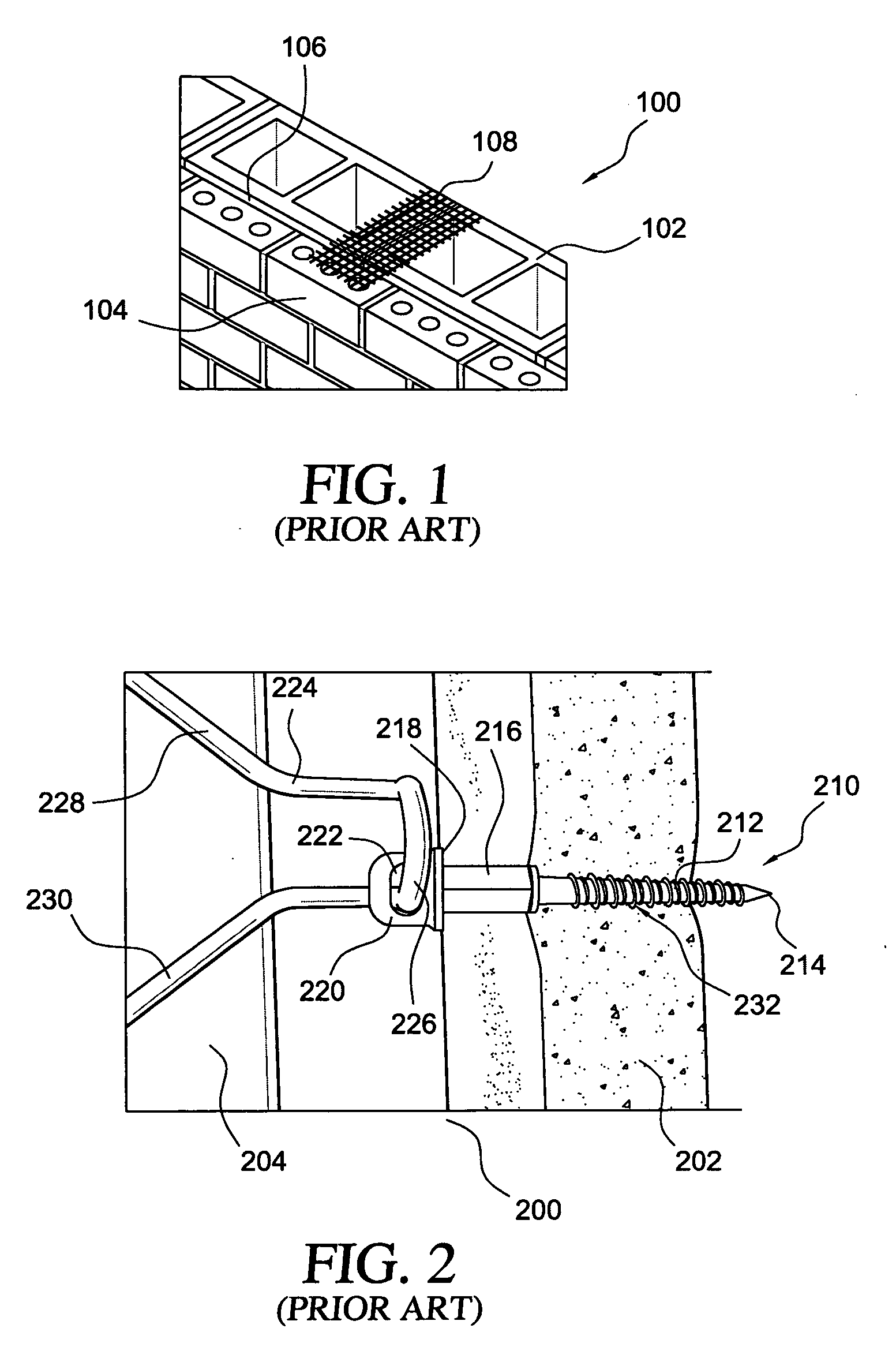
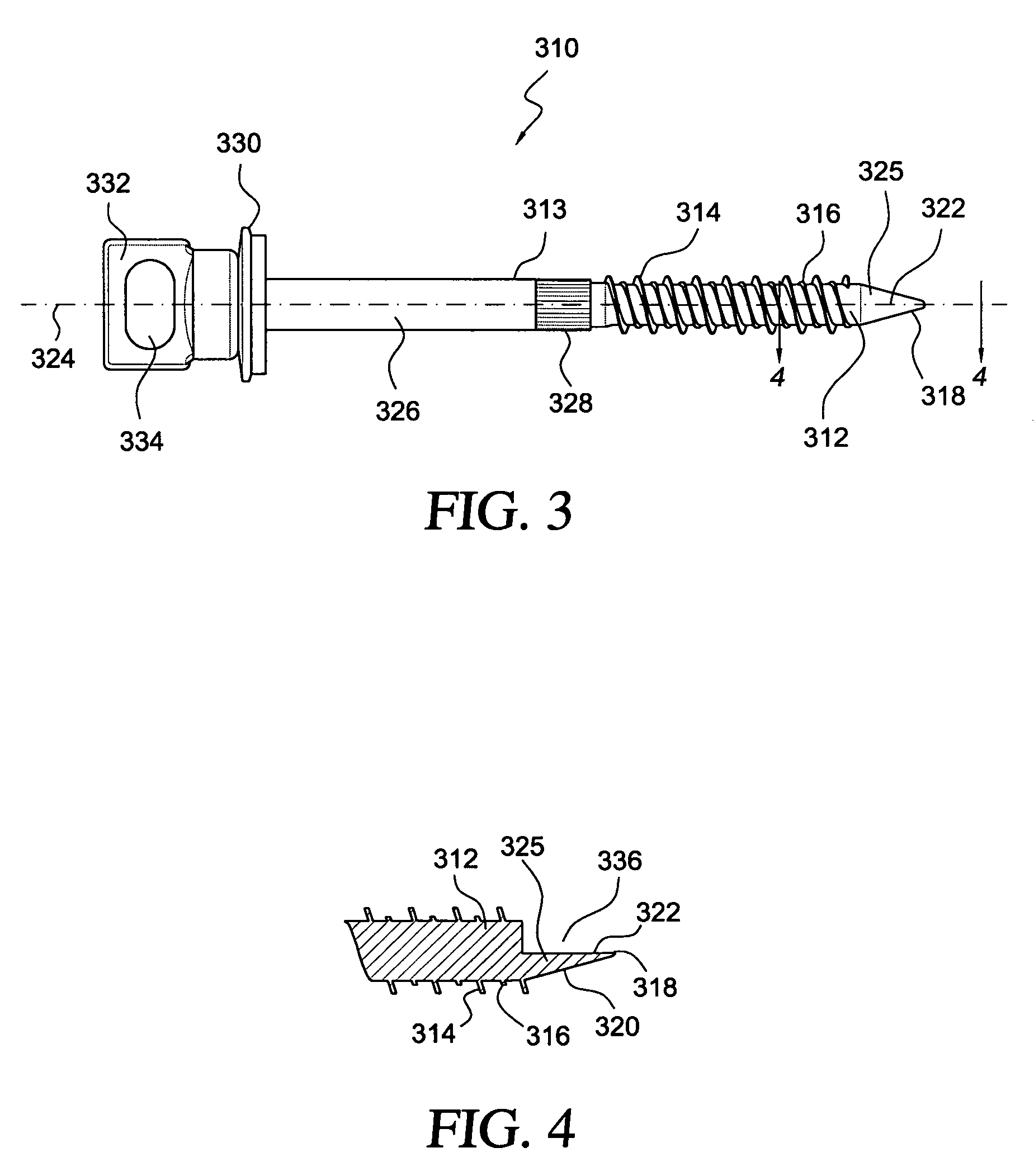
[0018]Referring now to the drawings, and more particularly to FIGS. 3 and 4 thereof, there is disclosed a first embodiment of a new and improved fastener which is adapted to be inserted into a wood substrate, and is likewise adapted to be inserted into a cinder block or concrete substrate so as to, for example, effectively secure an external wall structure, defined by means of a plurality of brick components, to an interior wall structure comprising a plurality of cinder block or concrete components, wherein the new and improved fastener is generally indicated by the reference character 310. The new and improved fastener 310 is somewhat similar to the conventional fastener as disclosed within FIG. 2, and therefore structural components of the first embodiment of the new and improved fastener 310 consistent with the present invention, which correspond to similar structural components of the conventional fastener 210, as illustrated within FIG. 2, will be designated by corresponding r...


PUM


Abstract

A new and improved fastener wherein the tip portion includes a unique and novel structure that enables and facilitates the insertion of the fastener into both wood and concrete substrates. The tip portion includes a half-cone structure in which a pointed tip is defined between a radially outer conical surface portion and a radially inner flat or planar surface portion.

Description

CROSS-REFERENCE TO RELATED PATENT APPLICATIONS[0001]This patent application is related to, based upon, and effectively a utility patent application conversion of U.S. Provisional Patent Application Ser. No. 61 / 006,549 which was filed on Jan. 18, 2008, the date-benefits of which are hereby claimed and the entirety of which is incorporated herein by reference to the extent permitted by law.FIELD OF THE INVENTION[0002]The present invention relates generally to screws and similar fasteners, and more particularly to a new and improved screw fastener wherein the tip portion comprises a unique and novel structure that enables and facilitates the insertion of the screw fastener into both wood and concrete substrates.BACKGROUND OF THE INVENTION[0003]Many different fasteners and other devices are known for securing, for example, brick components to cinder block or concrete structures in order to ensure that the brick components are in fact fixedly secured to the cinder block or concrete struc...

Claims


Application Information

Patent Timeline
IPC IPC(8): F16B25/10
CPCF16B25/0031F16B25/0068F16B45/00F16B25/103F16B35/06F16B25/0084
Inventor GONG, YONGPINGLATZ, MARKPANASIK, CHERYL L.DILL, MICHAEL
Owner ILLINOIS TOOL WORKS INC
Why Eureka
Try Eureka