Method and apparatus for indicating operational state of aircraft engine

a technology of aircraft engine and operational state, applied in the direction of instruments, navigation instruments, analogue processes for specific applications, etc., can solve the problems of inability to provide explicit or easy means to aid the crew in determining automation modes and submodes, introducing crew workload and error potential, and inappropriately interrupting and delaying crews, etc., to achieve easy easy, and quick determination

Active Publication Date: 2008-06-12
THE BOEING CO
View PDF23 Cites 26 Cited by
  • Summary
  • Abstract
  • Description
  • Claims
  • Application Information

AI Technical Summary

Benefits of technology

[0010]The present invention supports crew awareness and intervention / non-intervention response related decision making by providing information / indications that explicitly or implicitly help the crew readily, easily, and quickly determine at a glance engine start / recovery progress, the engine automation mode, and the operational state (e.g., subidle or running) of an aircraft engine. Optionally, information / indications can be provided that also help the crew readily, easily, and quickly determine at a glance how long engine start / recovery will likely take. The invention also has application in situations wherein the aircraft engine speed abnormally decreases toward a target idle running speed or for some other abnormal condition such as disagreement between commanded and indicated thrust.

Problems solved by technology

Currently, no explicit or easy means is provided to aid the crew in determining automation modes and submodes, if engine start / recovery is progressing normally, or how long start / recovery will likely take.
The resulting crew monitoring, detection, and interpretation tasks introduce crew workload and error potential.
The crew may inappropriately interrupt and delay, or terminate engine start.
Monitoring and detection tasks increase crew workload and divert crew attention away from the primary task of flying and navigating the aircraft.
Primary crew responsibilities, increasing levels and sophistication of engine automation designed to optimize engine start / recovery / operation, the broad range of possible operating conditions and circumstances, and the lack of explicit collocated engine automation and state indications, make correct / accurate crew interpretation of engine indications sometimes difficult.
Consequently, the crew must know, recall and typically estimate the engine parameter value at which the engine will be running, and / or divert time and effort to verify that the engine is running—often in a high workload or time critical situation.

Method used


Image

  • Method and apparatus for indicating operational state of aircraft engine
  • Method and apparatus for indicating operational state of aircraft engine
  • Method and apparatus for indicating operational state of aircraft engine

Examples


Embodiment Construction

[0022]The present disclosure describes methods and systems for displaying aircraft engine characteristics. Many specific details of certain embodiments of the invention are set forth in the following description and in FIGS. 4-7 to provide a thorough understanding of these embodiments. One skilled in the art, however, will understand that the present invention may have additional embodiments, and that the invention may be practiced without several of the details described below.

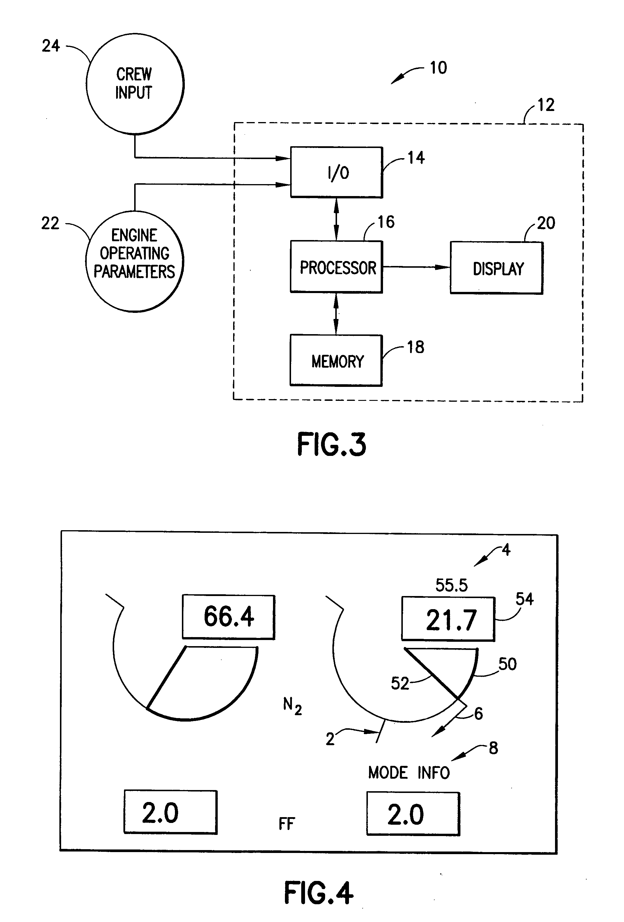
[0023]FIG. 3 is a schematic block diagram illustrating a system 10 that displays the state of one or more aircraft engines for viewing by the aircraft crew. The system 10 comprises a computer 12 having one or more input / output devices 14, a processor 16, a memory 18, and a display unit 20. In other embodiments, the functions carried out by the system 10 can be distributed over a plurality of computers or processing platforms. The input / output devices 14 can receive signals corresponding to engine automation a...


PUM


Abstract

A method and a system for indicating a target idle running speed, a predicted core speed, a predicted time to running, current engine state or automation modes of an operating aircraft engine, and indicating that the current core speed of the aircraft engine is less than a target idle running speed or is abnormally decreasing towards a target idle running speed. The indicators may be visual or aural. The visual indicators may include graphical or numeric symbols indicating the target idle running speed, the direction of core speed change, the predicted core speed at some future time, or current engine state or automation mode.

Description

TECHNICAL FIELD[0001]The present disclosure relates generally to methods and systems for indicating aircraft engine characteristics, such as the operational state of the engines, to the flight crew of the airplane.BACKGROUND[0002]Modern aircraft engine flight deck displays typically include computer-driven display screens dedicated to presenting engine status information. These display screens typically present to the pilots engine data indicating the values of a variety of engine operating parameters. For example, the display screens can present a primary engine display (shown in FIG. 1) and a secondary engine display (shown in FIG. 2).[0003]The primary engine display can present top-level engine parameter data, such as exhaust pressure ratio (EPR) display 30, fan speed (N1) display 32, and exhaust gas temperature (EGT) display 34. The primary engine display can include multiple sets of displays (two are shown in FIG. 1), one set for each engine of the aircraft.[0004]The secondary ...

Claims


Application Information

Patent Timeline
Patent Type & Authority Applications(United States)
IPC IPC(8): G08B29/00
CPCB64D43/00
Inventor CLARK, SAMUEL T.HOUCK, ANDREW W.SIKORA, JOSEPH A.BOWE, ROGLENDA R.
Owner THE BOEING CO
Why Eureka
Try Eureka