Device and method for addressing power to a load selected from a plurality of loads

a technology for addressing power and load, applied in the direction of circuit arrangement, ac network voltage adjustment, semiconductor lamp usage, etc., can solve the problems of high cost of solution, limited use of nanosecond time range, and inconvenient application in the field of solid state lighting applications

Inactive Publication Date: 2009-07-30
GENMAB AS +1
View PDF4 Cites 32 Cited by
  • Summary
  • Abstract
  • Description
  • Claims
  • Application Information

AI Technical Summary

Benefits of technology

[0004]It is an object of the present invention to provide a method and device for addressing power to at least a selected load from a plurality of loads, in particular light sources such as LED's or LED arrangements, without the requirement of large amounts of wires or logic.

Problems solved by technology

This solution has the disadvantage that it is complex and inconvenient to apply in the field of solid state lighting applications, since the number of wires grows proportionally with the amount of loads, i.e. light sources.
This solution has the disadvantage of being very expensive, since the amount of logic needed is proportional with the amount of loads as well.
This method has the disadvantage that its use is restricted to nanosecond time ranges, which are too small for lighting applications.

Method used


Image

  • Device and method for addressing power to a load selected from a plurality of loads
  • Device and method for addressing power to a load selected from a plurality of loads
  • Device and method for addressing power to a load selected from a plurality of loads

Examples


Embodiment Construction

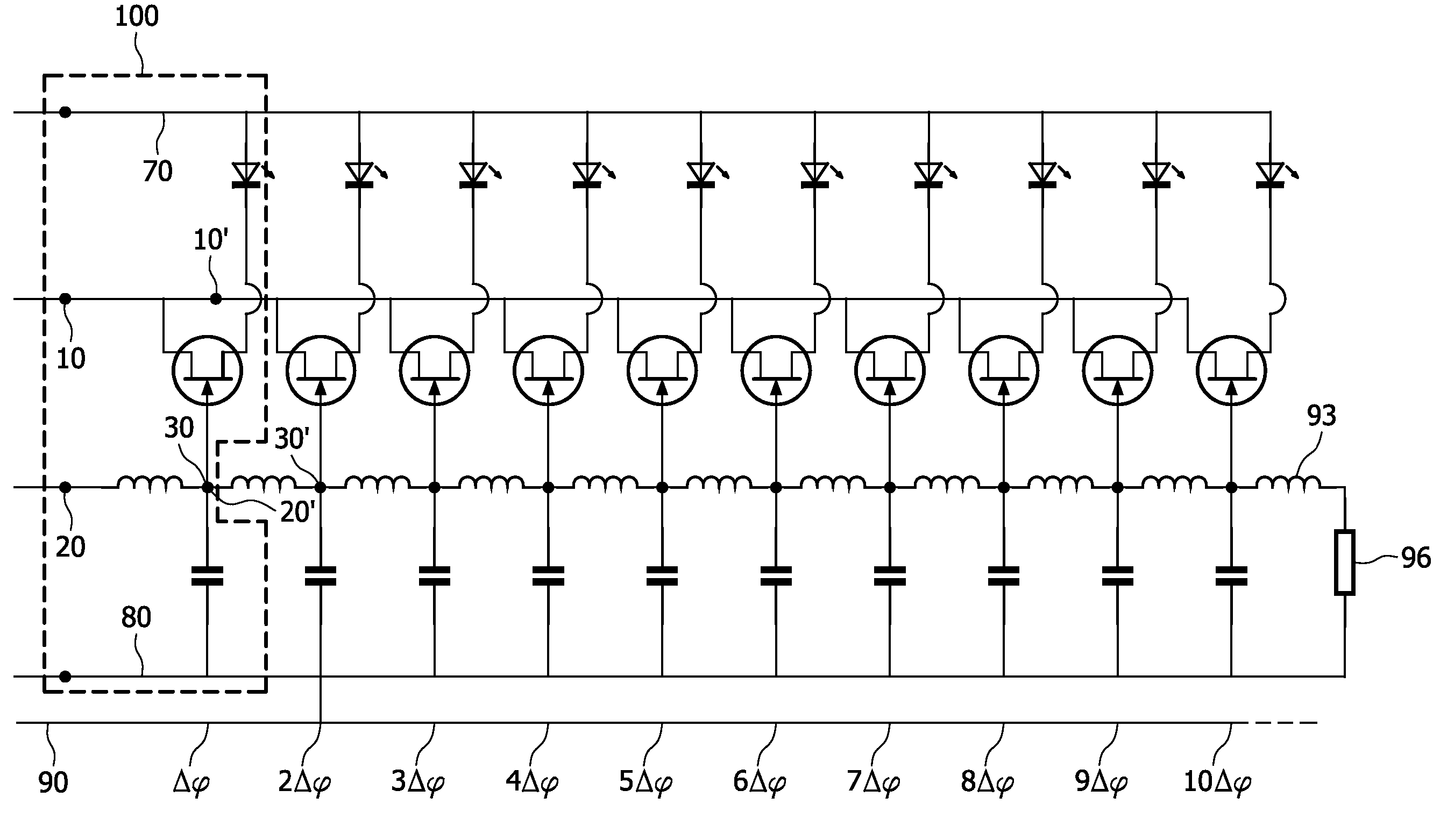
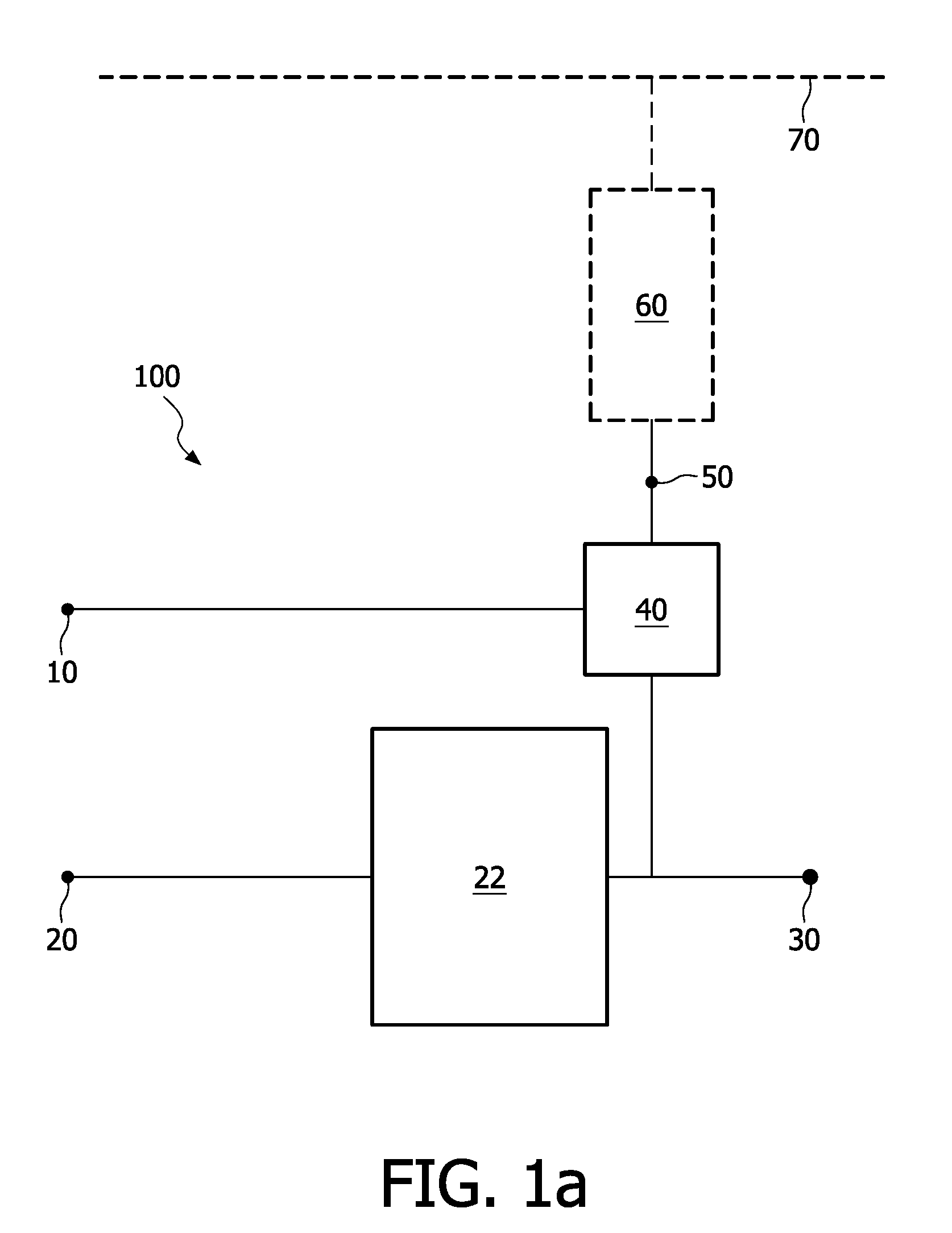
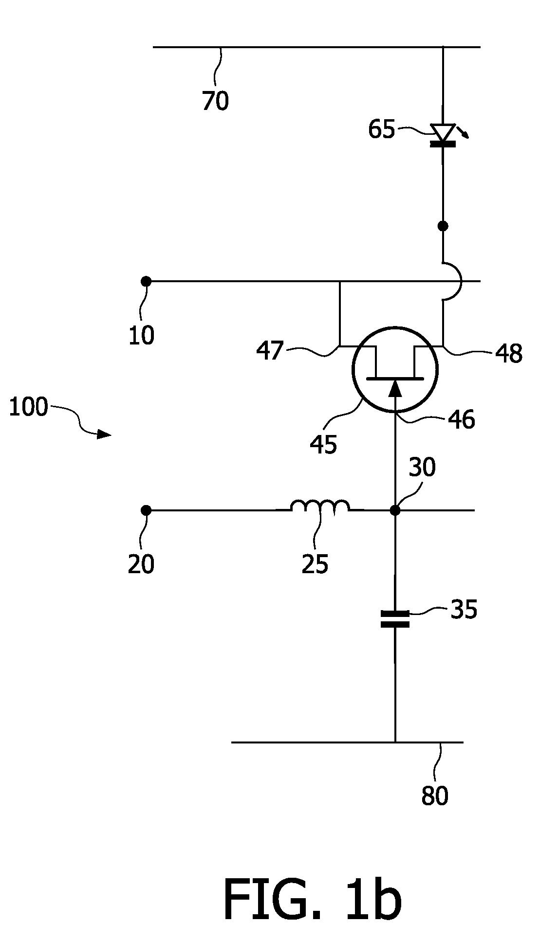
[0013]FIG. 1a shows a generic scheme of a subcircuit 100 for forming a circuit according to the present invention. The subcircuit comprises a first input terminal 10 for receiving a timed common power signal and a second input terminal 20 for receiving a clock signal with frequency f. The clock signal is output with a predetermined phase delay by delay element 22 to output 30 which is also connected to switching element 40 for switching the load. The switching element 40 is further coupled with the timed common power signal, and has a switching output 50 for being connected with a load. In FIG. 1a a dashed load 60, not being part of a general embodiment of the invention, is drawn between switching output 50 and dashed power supply line 70, which also does not form a part of a general embodiment of the invention.

[0014]Subcircuit 100 is configured to couple the switching output 50 with input 10, when a low value of the timed common power signal on input 10 coincides with a high value ...


PUM


Abstract

The invention relates to a device and method for addressing power to at least a selected load from a plurality of loads, in particular light sources in solid state lighting applications, such as decorative indoor and outdoor illumination for buildings or cars, by timing a power signal such as to power a selected load when said common timed power signal is switched to said load under control of a delayed clock signal.

Description

FIELD OF THE INVENTION[0001]The invention relates to a device and method for addressing power to at least a selected load from a plurality of loads, and in particular the invention relates to driving individual light sources in solid state lighting applications, such as decorative indoor and outdoor illumination for buildings or cars.BACKGROUND OF THE INVENTION[0002]In solid state lighting applications, such as decorative indoor and outdoor illumination for buildings or cars, decorative effects are generated by using large amounts of small light sources to illuminate relatively large areas. Surprising effects can be obtained by controlling and especially varying the luminescence of individual light sources in time. For independent control of multiple electrical loads, such as light sources, several solutions are known in the art. A simple solution is to provide separate wiring to each load to be controlled. This solution has the disadvantage that it is complex and inconvenient to ap...

Claims


Application Information

Patent Timeline
Patent Type & Authority Applications(United States)
IPC IPC(8): H02J3/14H05B44/00
CPCH05B33/0803Y02B20/346H05B33/0818Y02B20/30H05B45/32H05B45/3725
Inventor VERSCHUEREN, ALWIN ROGIER MARTIJN
Owner GENMAB AS
Why Eureka
Try Eureka