Method and apparatus for estimating/removing echo signal using channel coefficient predicting technique in multi-carrier system

a multi-carrier system and channel coefficient prediction technology, applied in multi-frequency code systems, repeater circuits, line-transmission details, etc., can solve problems such as difficult to select a region where installation is possible, deteriorating signal quality, and increasing installation costs of wireless repeaters

Active Publication Date: 2009-08-27
SAMSUNG ELECTRONICS CO LTD
View PDF4 Cites 30 Cited by
  • Summary
  • Abstract
  • Description
  • Claims
  • Application Information

AI Technical Summary

Problems solved by technology

The wireless repeater is equipment for primary use in a shadow region, such as a shielded space, an underground shopping center, a tunnel, and an underground parking lot, where it is not suitable to newly establish a base station or operate a relay vehicle.
However, when the wireless repeater transmits a radio signal to a mobile terminal, oscillation or a fine oscillation is generated due to the fact that an output signal of a transmission antenna returns, is re-input via a reception antenna and is amplified, thereby deteriorating signal quality.
However, this method causes the installation costs of a wireless repeater to increase and it is difficult to select a region where installation is possible in a scattering environment such as the downtown.
However, in a wireless repeater where a multi-carrier system is applied that does not guarantee the autocorrelation characteristic, it is difficult to accurately estimate an echo signal and prevent oscillation.
However, since a train signal section of the multi-carrier system is an extremely small portion of an entire signal section, when a time-variant characteristic of an echo channel cannot be ignored due to an influence of neighboring scattering objects, in an aspect of an installation environment of a wireless repeater, quality of interference-removed signal may be deteriorated by a channel change between a periodic time-division train signal section and the other sections.

Method used


Image

  • Method and apparatus for estimating/removing echo signal using channel coefficient predicting technique in multi-carrier system
  • Method and apparatus for estimating/removing echo signal using channel coefficient predicting technique in multi-carrier system
  • Method and apparatus for estimating/removing echo signal using channel coefficient predicting technique in multi-carrier system

Examples


Embodiment Construction

[0022]Preferred embodiments of the present invention are described in detail with reference to the accompanying drawings. The same or similar components may be designated by the same or similar reference numerals although they are illustrated in different drawings. Detailed descriptions of constructions or processes known in the art may be omitted to avoid obscuring the subject matter of the present invention.

[0023]Terms described below, which are defined considering functions in the present invention, can be different depending on user and operator's intention or practice. Therefore, the terms should be defined on the basis of the disclosure throughout this specification.

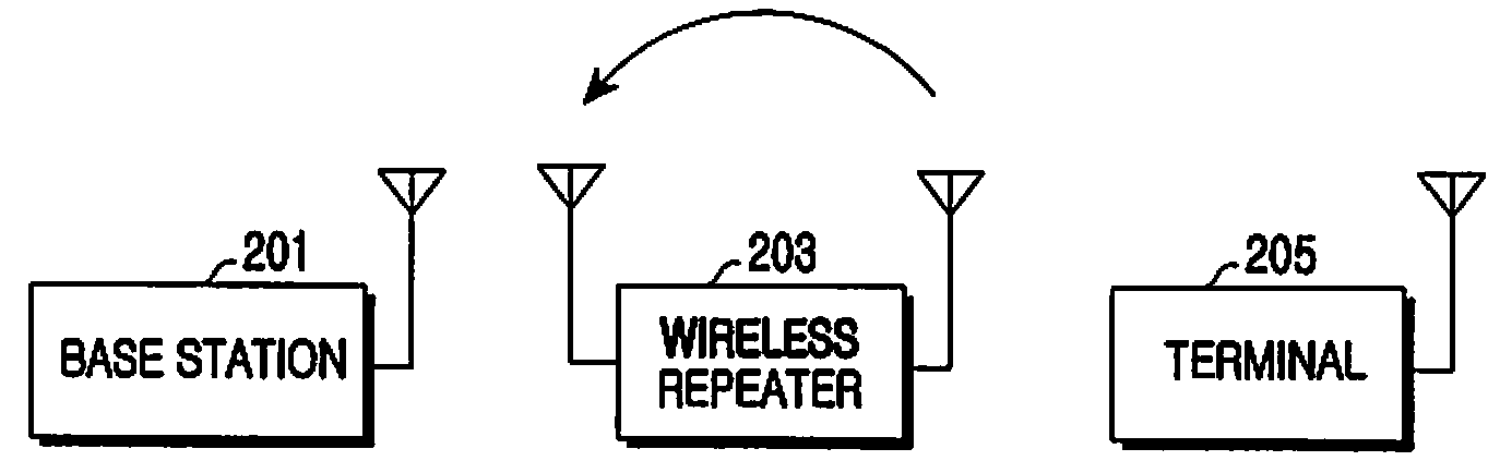
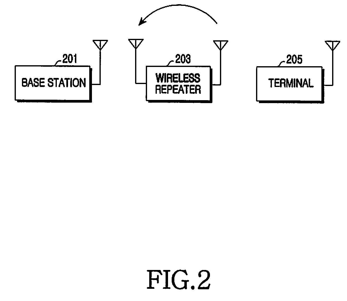
[0024]Embodiments of the present invention provide a method and an apparatus for predicting an echo channel generated in a section outside a train signal section in order to prevent oscillation and deterioration of signal quality by an echo signal at a wireless repeater operating in a multi-carrier system.

[0025]An ...


PUM


Abstract

A method and an apparatus are provided for estimating and removing interference of a signal at a wireless repeater operating in a multi-carrier system. In the method, a current echo channel linear prediction coefficient, which represents a coefficient between a current train signal section and a previous train signal section, is estimated using a current echo channel coefficient estimated in the current train signal section and a previous echo channel coefficient generated in the previous train signal section. A next echo channel coefficient is estimated using the current echo channel coefficient, the previous echo channel coefficient, and the current echo channel linear prediction coefficient. An echo channel coefficient outside a train signal section is estimated using the current echo channel coefficient and the next echo channel coefficient.

Description

PRIORITY[0001]This application claims priority under 35 U.S.C. §119 to an application filed in the Korean Intellectual Property Office on Feb. 25, 2008 and assigned Serial No. 10-2008-0016673, the contents of which are incorporated herein by reference.BACKGROUND OF THE INVENTION[0002]1. Field of the Invention[0003]The present invention relates generally to a method and an apparatus for estimating and removing an echo channel. The present invention relates particularly to a method and an apparatus for estimating the echo signal formed when an output signal of a transmission antenna of a wireless repeater returns and is re-input via a reception antenna, and transmitting, via the transmission antenna, a signal from which the estimated echo signal has been removed in advance.[0004]2. Description of the Related Art[0005]Mobile communication plays an important role in the development of an information-oriented society. It is optimal for a mobile communication system to allow a subscriber ...

Claims


Application Information

Patent Timeline
Patent Type & Authority Applications(United States)
IPC IPC(8): H04B7/165
CPCH04B7/15585H04B7/14H04L27/26
Inventor KU, JUNG-WOOKIM, JAE-BUMKANG, HEE-WONYOU, HWA-SUN
Owner SAMSUNG ELECTRONICS CO LTD
Why Eureka
Try Eureka