Die for die casting and method of manufacturing cast product

Inactive Publication Date: 2009-09-03
KK TOSHIBA
View PDF3 Cites 11 Cited by
  • Summary
  • Abstract
  • Description
  • Claims
  • Application Information

AI Technical Summary

Problems solved by technology

Here, the solidification time of molten metal of, for example, a magnesium alloy or the like is very short, and hence in a die-casting die having a small flow cross-sectional area (i.e., a cross-sectional area of a space through which molten metal flows), the

Method used


Image

  • Die for die casting and method of manufacturing cast product
  • Die for die casting and method of manufacturing cast product
  • Die for die casting and method of manufacturing cast product

Examples


Embodiment Construction

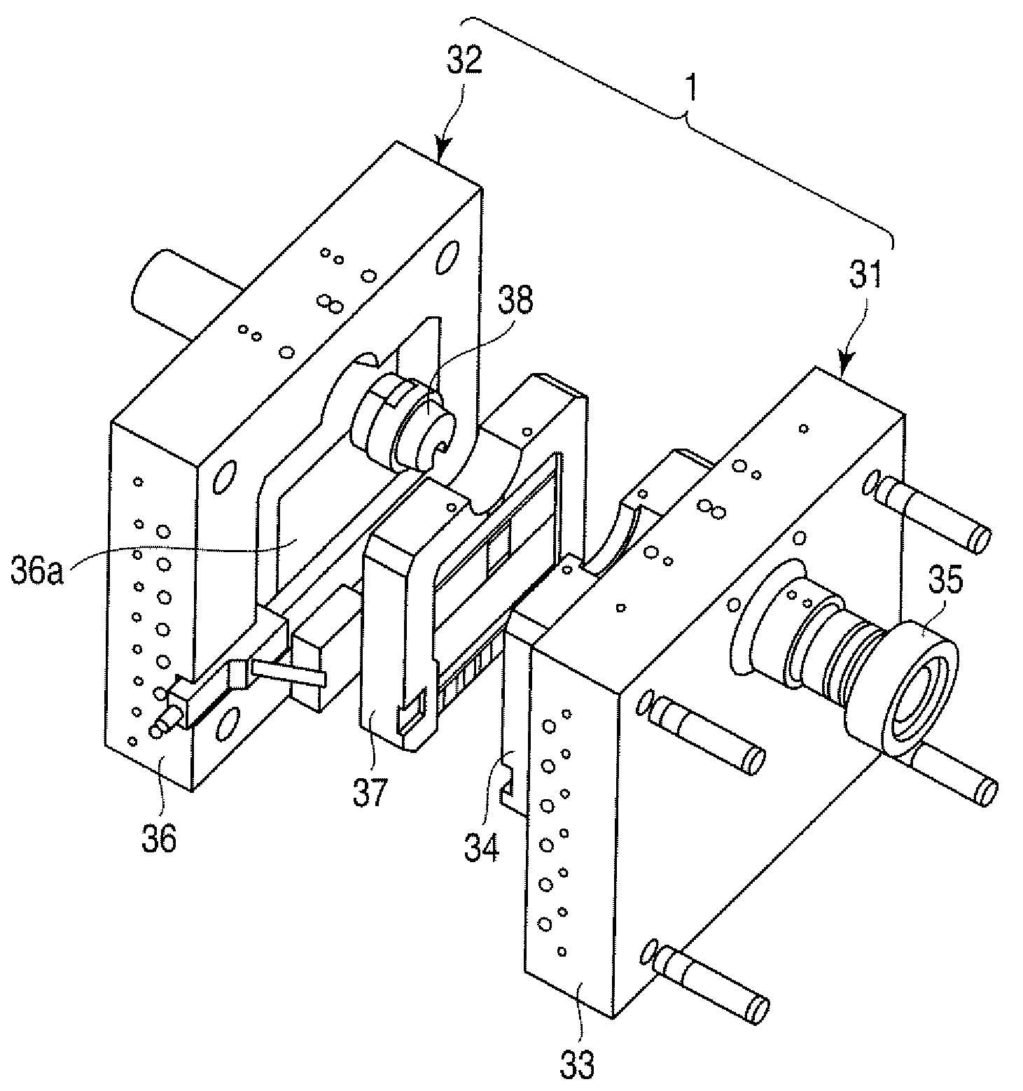
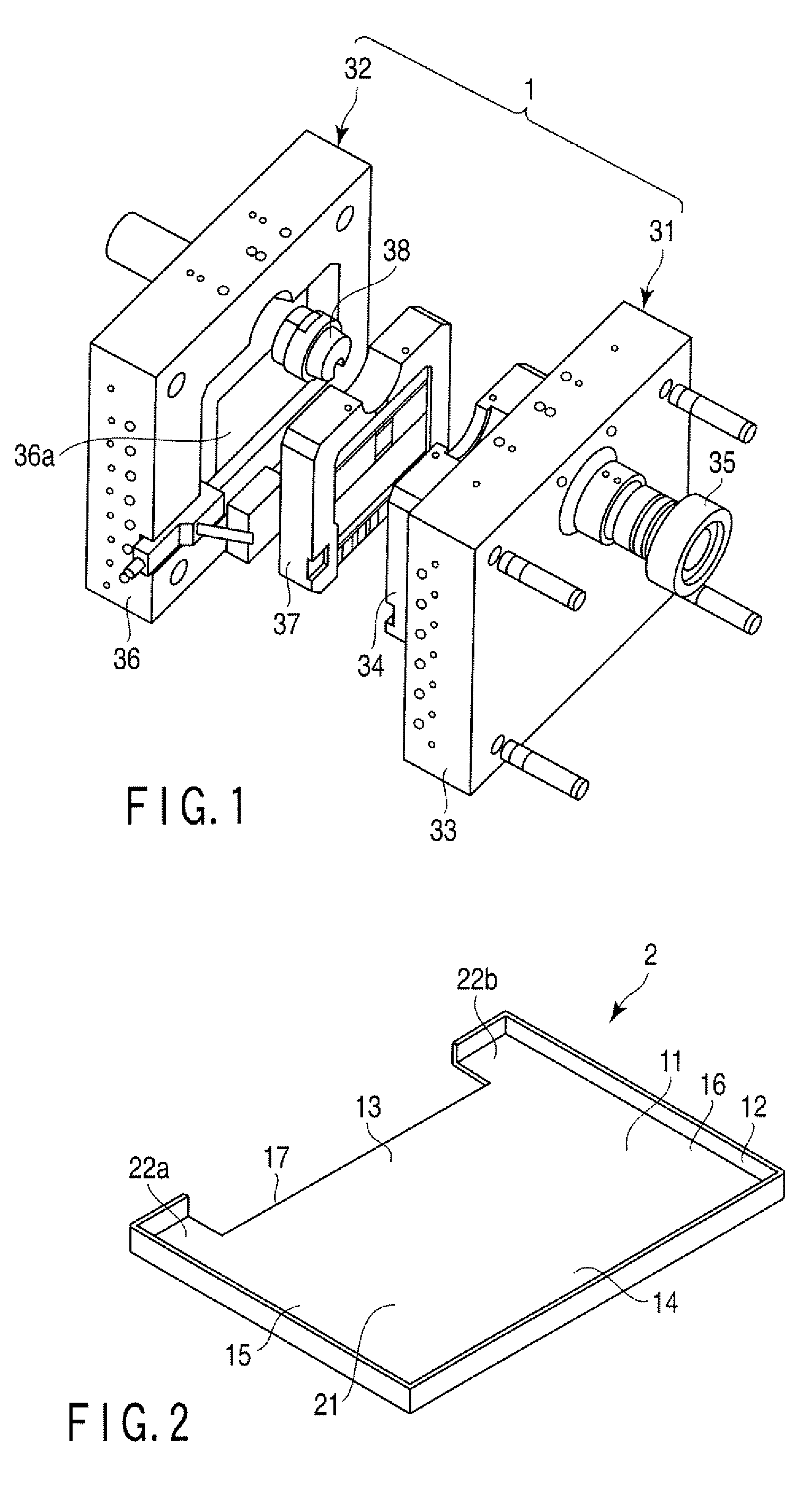
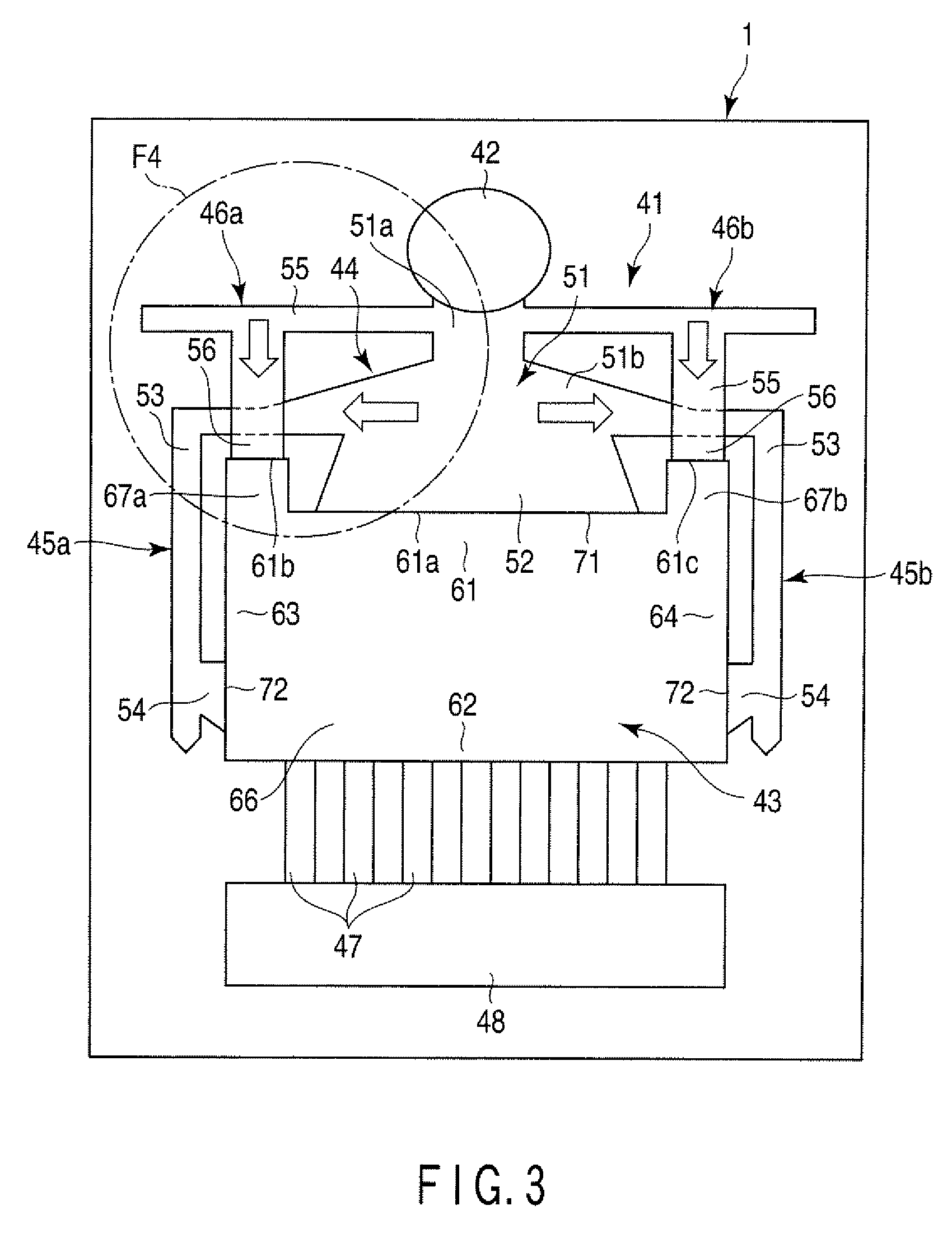
[0019]Various embodiments according to the invention will be described hereinafter with reference to the accompanying drawings. In general, according to one embodiment of the invention, a die for die casting comprises: a stationary die; and a movable die to be combined with the stationary die. When the movable die is combined with the stationary die, a biscuit section, a product section, a first runner, a first gate, a second runner, and a second gate are formed between the stationary die and the movable die. The biscuit section is a section into which molten metal is to be injected. The product section comprises a main product section, and a protrusion part which protrudes from the main product section toward a side of the biscuit section. The first runner is configured to guide the molten metal injected into the biscuit section toward the main product section. The first gate is provided between the first runner and the main product section at a position on a downstream side of the...


PUM


Abstract

According to one embodiment, a die includes a stationary die and a movable die. Between the stationary die and the movable die, a product section which includes a main product section, and a protrusion part protruding from the main product section toward a side of the biscuit section, a first runner configured to guide molten metal toward the main product section, and a second runner configured to guide molten metal toward the protrusion part are formed. The second runner is provided at a position deviated from the first runner three-dimensionally, and overpasses the first runner.

Description

CROSS-REFERENCE TO RELATED APPLICATIONS[0001]This application is based upon and claims the benefit of priority from Japanese Patent Application No. 2008-050568, filed Feb. 29, 2008, the entire contents of which are incorporated herein by reference.BACKGROUND[0002]1. Field[0003]One embodiment of the invention relates to a technique associated with die casting.[0004]2. Description of the Related Art[0005]A die-casting die of the cold-chamber die casting system comprises a biscuit section for receiving molten metal from an injection apparatus of a casting machine, a product section that is a space in which a product is to be cast, a main runner for guiding molten metal from the biscuit section toward the product section, and a main gate provided between the main runner and the product section, for accelerating the flow speed of the molten metal by sharply reducing the thickness.[0006]Here, the solidification time of molten metal of, for example, a magnesium alloy or the like is very sh...

Claims


Application Information

Patent Timeline
IPC IPC(8): B22D17/00
CPCB22D17/22
Inventor IKEDA, HIROSHIHIRAO, HIROAKI
Owner KK TOSHIBA
Why Eureka
Try Eureka