Pouring exhaust system of automobile component die-casting die and arrangement method

An exhaust system and die-casting mold technology, applied in the field of casting molds, can solve problems such as bulges on the surface of die-casting parts, and achieve the effects of avoiding gas engulfment in aluminum liquid, reducing the tendency of pores, and ensuring quality

Active Publication Date: 2019-02-01
宁波埃利特模具制造有限公司
View PDF13 Cites 4 Cited by
  • Summary
  • Abstract
  • Description
  • Claims
  • Application Information

AI Technical Summary

Problems solved by technology

[0002] attached figure 2 Shown is a large-scale die-casting automobile component, and the automobile component includes: a main body 14 and a side body 15 connected to one side of the main body, a first gap 16 arranged at one end of the main body, one side of the main body and a side body The second gap 17 formed between the sides; the overall dimensions of the automobile component: length X width X height is 627mmX618mmX256mm, the basic wall thickness is 2.5-3mm, and the weight is 2976g. After die-casting, T6 heat treatment (aluminum alloy solution treatment plus full artificial aging) ;Because the shape of the automobile component is irregular and the wall thickness is relatively thin, the automobile component is produced with a die-casting mold with a traditional pouring exhaust system, and there are deficiencies that air holes are easily generated inside the die-casting part, and bulges are easily generated on the surface of the die-casting part after T6 heat treatment; Therefore, it is an urgent problem to design a pouring exhaust system and setting method for the die-casting mold of an automobile component that does not produce pores inside the die-casting and does not produce bulges on the surface of the die-casting after T6 treatment.

Method used


Image

  • Pouring exhaust system of automobile component die-casting die and arrangement method
  • Pouring exhaust system of automobile component die-casting die and arrangement method

Examples


Embodiment Construction

[0017] The present invention will be further described below in conjunction with the accompanying drawings.

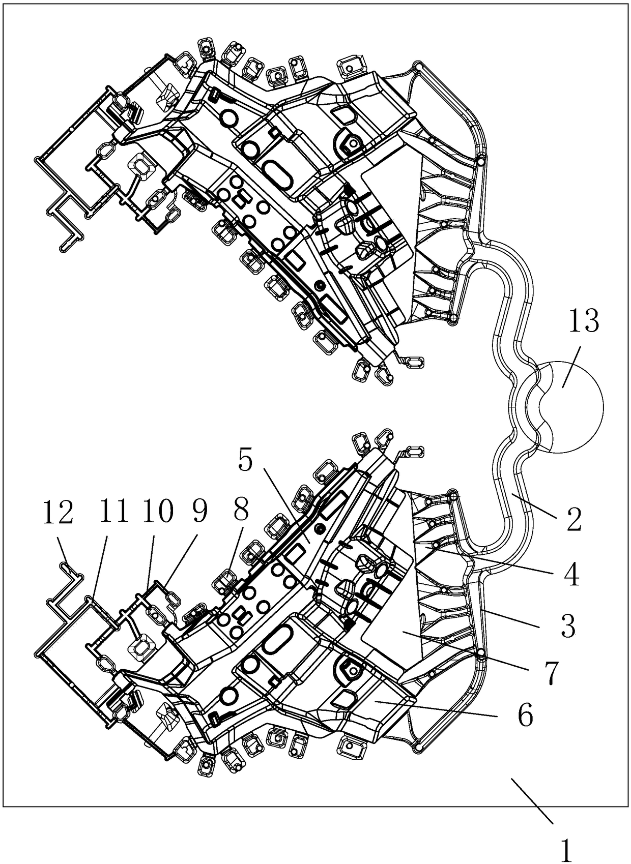
[0018] as attached figure 1 Shown: a pouring exhaust system for a die-casting mold of an automobile component, including: a die-casting mold body 1, at least one of which is arranged in the die-casting mold body 1 and is provided with a sprue 2, a runner 3, and seven ingates 4 The mold cavity; the mold cavity includes: a main body cavity 5, a side body cavity 6 communicated with one side of the body cavity 5, and an auxiliary cavity whose inner end communicates with one end of the body cavity 5, one side of the body cavity 5, and one side of the side body cavity 6, respectively. Inlet cavity 7, twenty-three slag cavity 8; the inner end of ingate 4 communicates with the outer end of side body cavity 6 or the outer end of auxiliary inflow cavity 7; the thickness of auxiliary inflow cavity 7 is 1 / 2 0.8 times; the thickness of ingate 4 is equal to the thickness of auxili...


PUM

PropertyMeasurementUnit
diameteraaaaaaaaaa

Abstract

The invention relates to a pouring exhaust system of an automobile component die-casting die and an arrangement method. The pouring exhaust system of the automobile component die-casting die comprisesa die-casting die body and cavities, wherein the one or more cavities are formed in the die-casting die body, and each cavity is provided with a sprue, a cross gate and multiple flow gates. Each cavity comprises a main body cavity, a side body cavity, an auxiliary gating cavity and multiple cinder ladle cavities, wherein the inner ends of each auxiliary gating cavity communicate with one end of the corresponding main body cavity, one side of the corresponding main body cavity and one side of the corresponding side body cavity. The inner end of each flow gate communicates with the outer end ofthe corresponding side body cavity or the outer end of the corresponding auxiliary gating cavity. The thickness of each auxiliary gating cavity and the thickness of each flow gate are each 0.7-0.85 times the wall thickness of each die-casting die cavity. The sectional area of each sprue is less than that of the corresponding cross gate. The sectional area of each cross gate is less than the totalsectional area of the multiple flow gates. Each cinder ladle cavity communicates with the periphery of the corresponding main body cavity or the corresponding side body cavity. By means of the pouring exhaust system of the automobile component die-casting die, air holes cannot be generated inside die castings; and the surfaces of the die castings obtained after T6 treatment cannot bulge.

Description

technical field [0001] The invention relates to the field of casting molds, in particular to a pouring exhaust system and a setting method for die-casting molds of automobile components. Background technique [0002] attached figure 2 Shown is a large-scale die-casting automobile component, and the automobile component includes: a main body 14 and a side body 15 connected to one side of the main body, a first gap 16 arranged at one end of the main body, one side of the main body and a side body The second gap 17 formed between the sides; the overall dimensions of the automobile component: length X width X height is 627mmX618mmX256mm, the basic wall thickness is 2.5-3mm, and the weight is 2976g. After die-casting, T6 heat treatment (aluminum alloy solution treatment plus full artificial aging) ;Because the shape of the automobile component is irregular and the wall thickness is relatively thin, the automobile component is produced with a die-casting mold with a traditional p...

Claims


Application Information

Patent Timeline
Patent Type & Authority Applications(China)
IPC IPC(8): B22D17/22
CPCB22D17/22B22D17/2272
Inventor 徐敏志
Owner 宁波埃利特模具制造有限公司
Why Eureka
Try Eureka