Printed circuit board

Active Publication Date: 2009-09-03
NITTO DENKO CORP
View PDF8 Cites 12 Cited by
  • Summary
  • Abstract
  • Description
  • Claims
  • Application Information

AI Technical Summary

Benefits of technology

[0019]An object of the present invention is to provide a printed circuit

Problems solved by technology

This may cause a transmission error of a differential signal through the write conductors W1,

Method used


Image

  • Printed circuit board
  • Printed circuit board
  • Printed circuit board

Examples


first embodiment

(1-1) Configuration of the Suspension Board

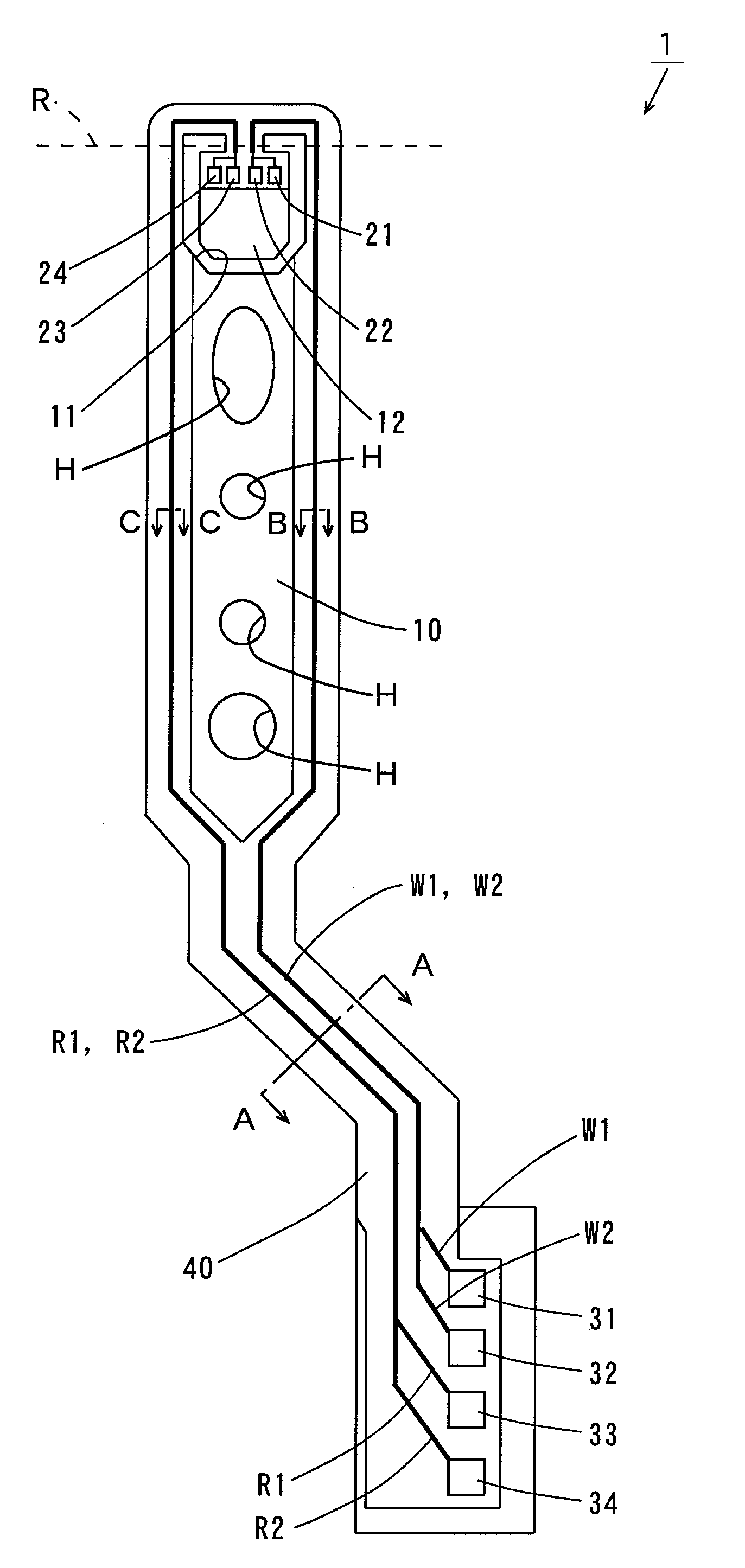
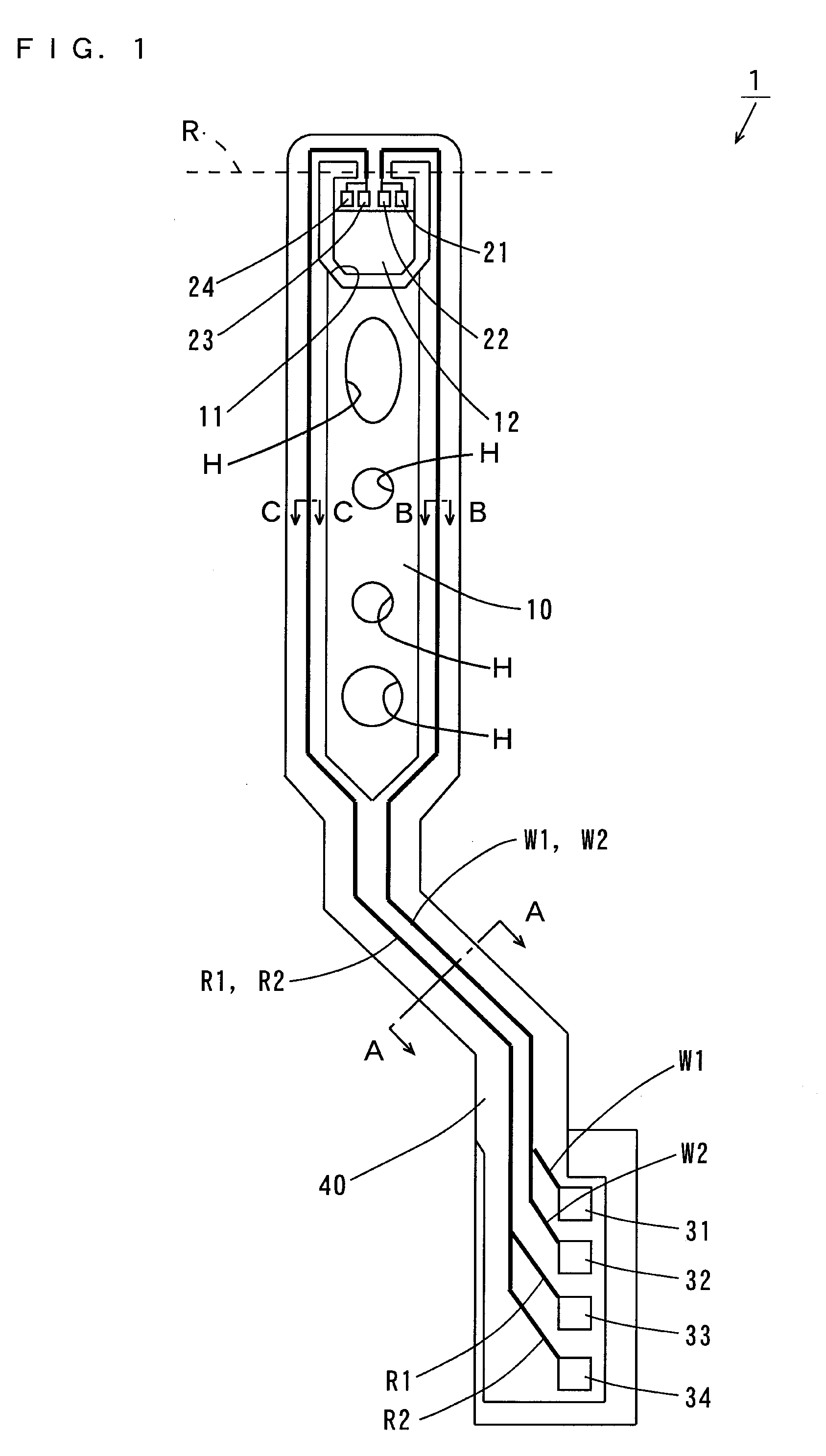
[0053]FIG. 1 is a top view of the suspension board according to a first embodiment of the present invention, and FIG. 2 is a vertical sectional view of the suspension board 1 of FIG. 1. Note that in FIG. 2, (a) shows a sectional view taken along the arrowed line A-A of FIG. 1, (b) shows a sectional view taken along the arrowed line B-B, and (c) shows a sectional view taken along the arrowed line C-C.

[0054]As shown in FIG. 1, the suspension board 1 includes a suspension body 10 formed of a long-sized metal substrate. Write wiring traces W1, W2 and read wiring traces R1, R2 are formed on the suspension body 10 as indicated by the thick solid lines.

[0055]At an end of the suspension body 10, a U-shaped opening 11 is formed, thereby providing a magnetic head supporting portion (hereinafter referred to as a tongue) 12. The tongue 12 is bent along the broken line R to form a predetermined angle with respect to the suspension body 10. Four electrod...

second embodiment

[0106]FIG. 5 is a vertical sectional view showing a suspension board according to a second embodiment of the present invention. Note that in FIG. 5, (a) shows a sectional view taken along the arrowed line A-A of FIG. 1, (b) shows a sectional view taken along the arrowed line B-B, and (c) shows a sectional view taken along the arrowed line C-C.

[0107]The suspension board 2 according to the present embodiment is different from the suspension board 1 of FIG. 2 in the following points.

[0108]As shown in FIG. 5 (a), in the present embodiment, a ground trace G3 is formed between the write wiring trace W2 and the read wiring trace R2 on the third insulating layer 43 in the sectional view taken along the arrowed line A-A.

[0109]In this case, the ground trace G3 sufficiently prevents occurrence of the crosstalk between the write wiring traces W1, W2 and the read wiring traces R1, R2.

[0110]In addition, the ground trace G3 is formed on the other side of the write wiring trace W2 in the cross sect...


PUM


Abstract

A first insulating layer is formed on a suspension body, and a write wiring trace is formed on the first insulating layer. A second insulating layer is formed on the first insulating layer so as to cover the wiring trace. A write wiring trace is formed, above the write wiring trace, on the second insulating layer. A ground trace is formed on one side of the write wiring trace at a distance on the second insulating layer. A third insulating layer is formed on the second insulating layer so as to cover the wiring trace and the ground trace. An opening is formed in a region, below the write wiring trace, of the suspension body.

Description

BACKGROUND OF THE INVENTION[0001]1. Field of the Invention[0002]The present invention relates to a printed circuit board.[0003]2. Description of the Background Art[0004]An actuator is used in a drive such as a hard disk drive.[0005]Such an actuator includes an arm arranged rotatably with respect to a rotation shaft and a suspension board used for a magnetic head that is attached to the arm. The suspension board is a printed circuit board for aligning the magnetic head with a desired track of a magnetic disk.[0006]FIG. 6 is a vertical sectional view showing one example of a conventional suspension board. In the suspension board 900 of FIG. 6, an insulating layer 903 is formed on a metal substrate 902. A pair of write conductors W1, W2 and a pair of read conductors R1, R2 are formed so as to align in sequence on the insulating layer 903.[0007]One ends of the conductors W1, W2, R1, R2 are connected to a magnetic head (not shown). The other ends of the conductors W1, W2, R1, R2 are elec...

Claims


Application Information

Patent Timeline
IPC IPC(8): H05K1/11
CPCG11B5/4853G11B5/486H05K1/0219H05K1/0224H05K1/0245H05K2201/0969H05K1/0253H05K1/056H05K2201/09236H05K2201/09672H05K1/0248G11B5/484
Inventor HONJO, MITSURUKAMEI, KATSUTOSHI
Owner NITTO DENKO CORP
Why Eureka
Try Eureka