Printed circuit board having a layered signal line pair, a suspension board

a printed circuit board and signal line pair technology, applied in the field of printed circuit boards, can solve problems such as transmission error and transmission error, and achieve the effect of sufficiently preventing transmission error

Active Publication Date: 2011-07-26
NITTO DENKO CORP
View PDF9 Cites 23 Cited by
  • Summary
  • Abstract
  • Description
  • Claims
  • Application Information

AI Technical Summary

Benefits of technology

[0018]An object of the present invention is to provide a printed circuit board in which a signal transmission error can be sufficiently prevented.

Problems solved by technology

This may cause a transmission error of a differential signal through the write conductors W1, W2 and a transmission error of a differential signal through the read conductors R1, R2.

Method used


Image

  • Printed circuit board having a layered signal line pair, a suspension board
  • Printed circuit board having a layered signal line pair, a suspension board
  • Printed circuit board having a layered signal line pair, a suspension board

Examples


first embodiment

[0046](1) Configuration of the Suspension Board

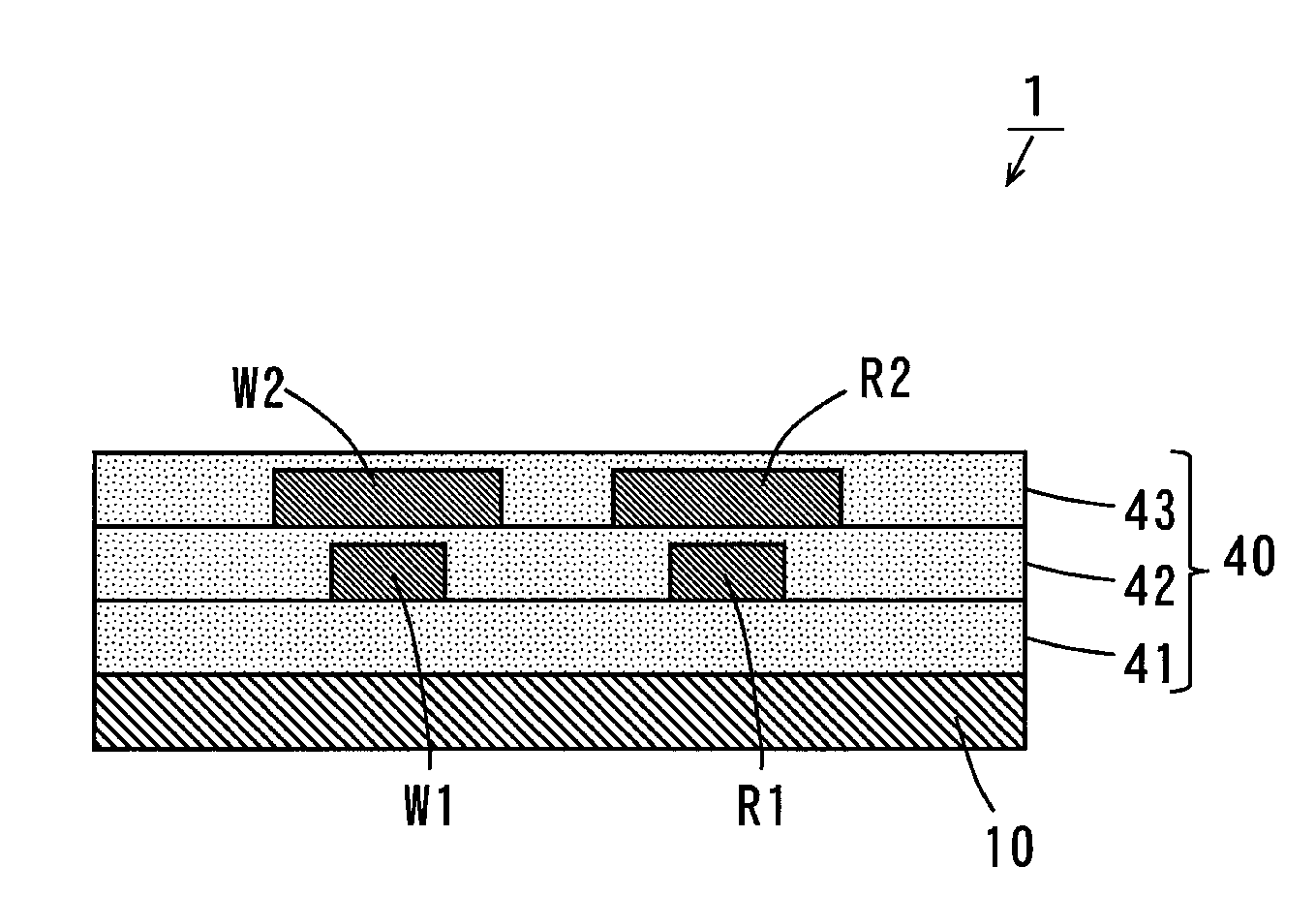
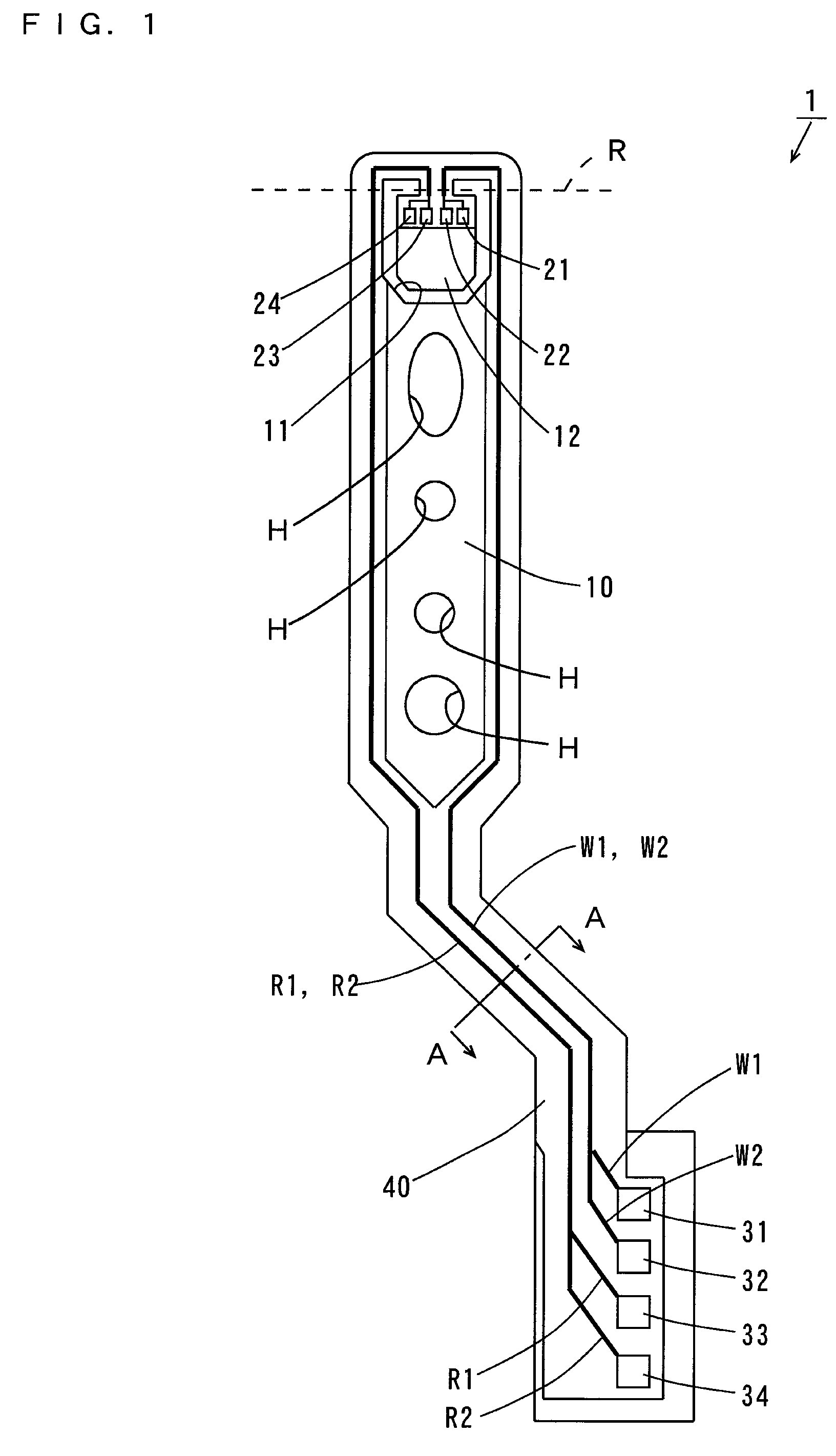
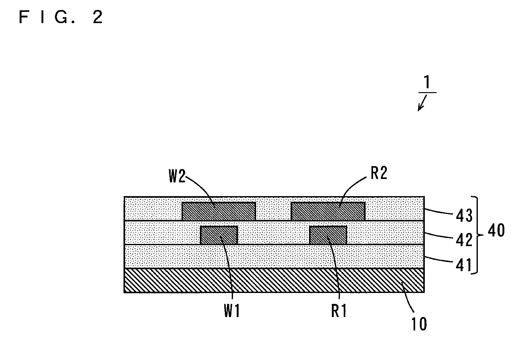
[0047]FIG. 1 is a top view of the suspension board according to a first embodiment of the present invention, and FIG. 2 is a vertical sectional view of the suspension board 1 taken along the line A-A of FIG. 1.

[0048]As shown in FIG. 1, the suspension board 1 includes a suspension body 10 formed of a long-sized metal substrate. Write wiring traces W1, W2 and read wiring traces R1, R2 are formed on the suspension body 10 as indicated by the thick solid lines.

[0049]At an end of the suspension body 10, a U-shaped opening 11 is formed, thereby providing a magnetic head supporting portion (hereinafter referred to as a tongue) 12. The tongue 12 is bent along the broken line R to form a predetermined angle with respect to the suspension body 10. Four electrode pads 21, 22, 23, 24 are formed at an end of the tongue 12.

[0050]Four electrode pads 31, 32, 33, 34 are formed at the other end of the suspension body 10. The electrode pads 21 to 24 on th...

second embodiment

[0093]A suspension board according to a second embodiment is different from the suspension board 1 according to the first embodiment in the following points.

[0094]FIG. 5 is a sectional view of the suspension board 2 according to the second embodiment.

[0095]As shown in FIG. 5, an auxiliary wiring trace 50 is provided between the write wiring trace W1 and the read wiring trace R1 on the first insulating layer 41 in the present embodiment.

[0096]In this case, an upper surface of a region, between the write wiring trace W1 and the read wiring trace R1, of the second insulating layer 42 can be prevented from bending in a concave shape at the time of formation of the second insulating layer 42. This prevents generation of defects in the write wiring trace W2 and the read wiring trace R2 at the time of formation of the write wiring trace W2 and the read wiring trace R2 on the second insulating layer 42. As a result, the yield of the suspension board 2 can be improved.

[0097]Note that the aux...


PUM

PropertyMeasurementUnit
thickness t1aaaaaaaaaa

Abstract

A first insulating layer is formed on a suspension body, and a write wiring trace and a read wiring trace are formed on the first insulating layer. A second insulating layer is formed on the first insulating layer so as to cover the wiring traces. A write wiring trace and a read wiring trace are formed on the second insulating layer. A third insulating layer is formed on the second insulating layer so as to cover the wiring traces. The width of the wiring trace is larger than the width of the wiring trace, and the width of the wiring trace is larger than the width of the wiring trace.

Description

BACKGROUND OF THE INVENTION[0001]1. Field of the Invention[0002]The present invention relates to a printed circuit board.[0003]2. Description of the Background Art[0004]An actuator is used in a drive such as a hard disk drive. Such an actuator includes an arm arranged rotatably with respect to a rotation shaft and a suspension board used for a magnetic head that is attached to the arm. The suspension board is a printed circuit board for aligning the magnetic head with a desired track of a magnetic disk.[0005]FIG. 6 is a vertical sectional view showing one example of a conventional suspension board. In the suspension board 900 of FIG. 6, an insulating layer 903 is formed on a metal substrate 902. A pair of write conductors W1, W2 and a pair of read conductors R1, R2 are formed so as to align in sequence on the insulating layer 903.[0006]One ends of the conductors W1, W2, R1, R2 are connected to a magnetic head (not shown). The other ends of the conductors W1, W2, R1, R2 are electrica...

Claims


Application Information

Patent Timeline
Patent Type & Authority Patents(United States)
IPC IPC(8): G11B21/16
CPCG11B5/4853G11B5/486H05K1/0248H05K1/0245H05K1/056H05K2201/0352H05K2201/09672H05K2201/09727G11B5/484
Inventor KAMEI, KATSUTOSHIHO, VOONYEE
Owner NITTO DENKO CORP
Why Eureka
Try Eureka