Optical information reproducing method, optical information reproducing device, and optical information recording medium

a technology of optical information and reproducing method, which is applied in the field of high-capacity optical disc techniques, can solve the problems of increasing the bit error rate, insufficient amplitude for carrying out stable tracking servo, etc., and achieves the effect of increasing the density and capacity of recording data

Inactive Publication Date: 2009-03-26
HITACHI CONSUMER ELECTRONICS CORP
View PDF9 Cites 5 Cited by
  • Summary
  • Abstract
  • Description
  • Claims
  • Application Information

AI Technical Summary

Benefits of technology

[0037]For the super-resolution reproduction technology that enables the reproduction of a mark smaller than the optical resolution and thereby achieves a further increase in the density and capacity of the recording data, a reproduction laser power for obtaining a high-quality reproduction signal and tracking signal can be determined.

Problems solved by technology

Since a push-pull signal obtained in this case has an amplitude comparable to that of a push-pull signal obtained from a substrate having a small track pitch in an ordinary optical disc, this amplitude is insufficient for carrying out stable tracking servo.
If the size of a super-resolution area in the medium radial direction becomes extremely large, the reproduction signal is overlapped by a signal of the adjacent track, thereby increasing the bit error rate.

Method used


Image

  • Optical information reproducing method, optical information reproducing device, and optical information recording medium
  • Optical information reproducing method, optical information reproducing device, and optical information recording medium
  • Optical information reproducing method, optical information reproducing device, and optical information recording medium

Examples


first embodiment

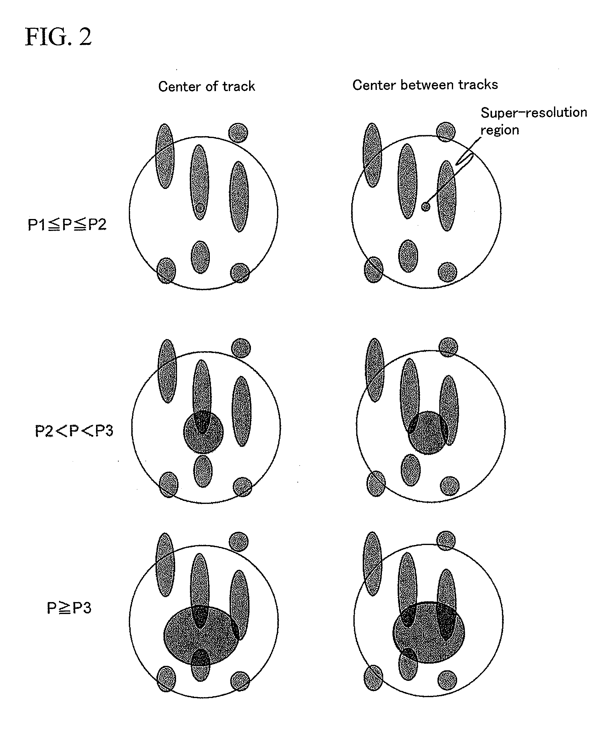
[0041]As a first embodiment, a case where the upper and lower levels of an envelope of a cross track signal are observed is described.

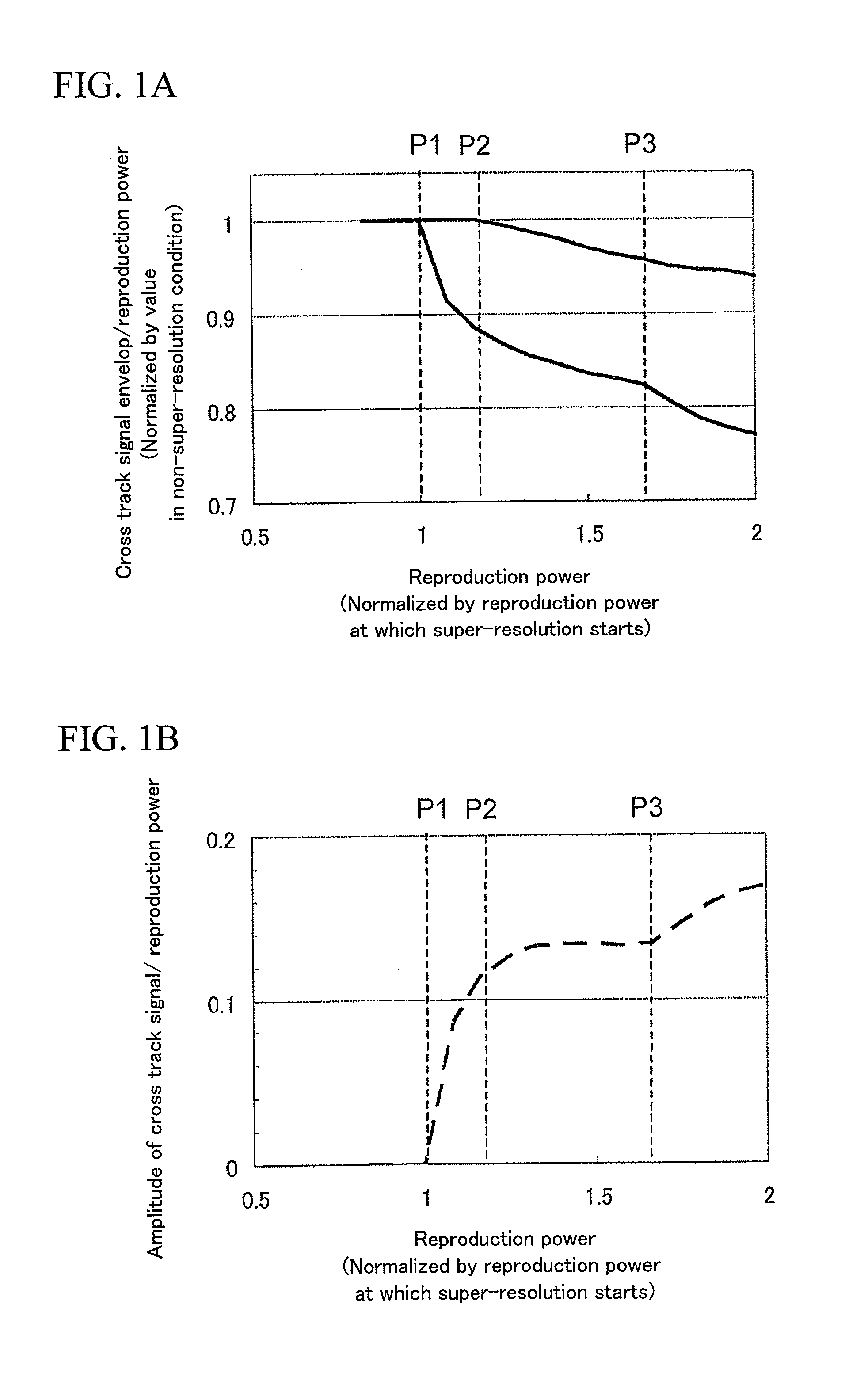
[0042]First, a method for fabricating a disc is described hereinafter. Here, the case of a ROM disc is described. In order to fabricate the ROM disc, data is recorded using an electron beam lithography apparatus. An electron beam resist is applied in a thickness of 100 nm onto a silicon substrate. A pattern corresponding to a recording data is drawn with an electron beam while rotating the substrate. The modulation code used here is 1-7 PP with a time window width of 25 nm, and the shortest mark length is 50 nm. The mark width is set to 100 nm and the track pitch is set to 200 nm. The recording data includes the values of P2 and P3 shown in FIGS. 1A and 1B. This data is recorded in regions of 24 mm and 58 mm radially from the center of the disc. Furthermore, in the disc radius from 25 mm to 25.5 mm and the disc radius from 57.5 mm to 58 mm, a predeter...

second embodiment

[0052]Next, a second embodiment is described. Here, a means for observing the amplitude of a cross track signal is described.

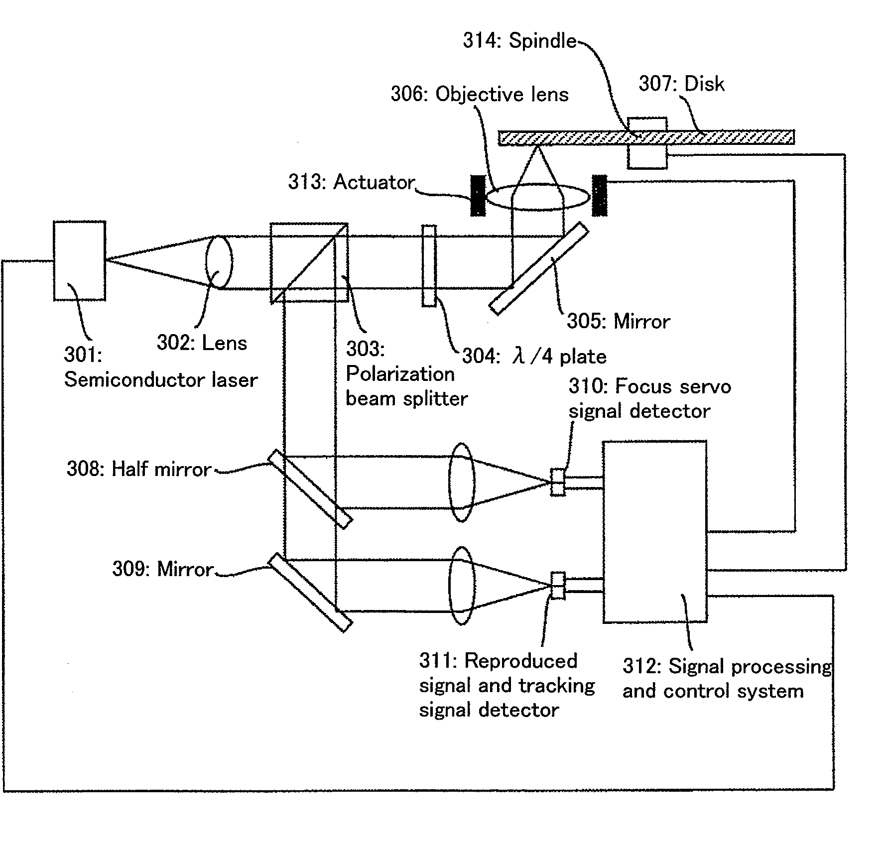
[0053]The disc is fabricated using the same method as the first embodiment. Moreover, the configuration of the drive is the same as the first embodiment except the signal processing and control system 312 of FIG. 3.

[0054]The disc is rotated inside the drive as in the first embodiment, and the data regarding the values of P2 and P3 recorded on the disc is read and then the light spot is moved to a portion in which the predefined data sequence is recorded.

[0055]The cross track signal is acquired as in the first embodiment, and the amplitude thereof is calculated in the signal processing and control system 312. As in the first embodiment, the differential coefficient of the amplitude of the cross track signal when the reproduction power is increased from 2.0 mW to 3 mW by a step increment of 0.05 mW is calculated. Here, as in the first embodiment, let the amplitu...

third embodiment

[0061]In the process of detecting a cross track signal while increasing the reproduction power in order to identify P2 and P3 in the third embodiment, the push-pull signal is detected at the same time. The push-pull signal described here is a value normalized by a total quantity of signals. In the drive used here, it is known that if the amplitude of the push-pull signal is greater than 1.5 V, the tracking servo is sufficiently stabilized, but the reproduction power at which the amplitude of the push-pull signal becomes greater than 1.5 V is in the range from 2.45 mW to 2.7 mW.

[0062]The tracking servo is applied at 2.45 mW, and the reproduction power is increased up to 2.7 mW by a step increment of 0.05 mW, and when the bit error rate of a mark sequence having a predetermined pattern is measured, the bit error rate becomes the minimum at 2.65 mW. Thus, the optimum reproduction power is determined as 2.65 mW.

[0063]Furthermore, a fifth embodiment is described. Here, the optimum reprod...


PUM

PropertyMeasurementUnit
diameteraaaaaaaaaa
diameteraaaaaaaaaa
diameteraaaaaaaaaa

Abstract

In a super-resolution optical disk for the purpose of achieving an increase in the density of recording data by reproducing a recording mark smaller than optical resolution, the optimum reproduction power needs to be determined since the quality of a super-resolution reproduced signal strongly depends on the reproduction laser power. However, since the track error signal required for tracking servo also depends on the reproduction power, there is a need for a method for determining the reproduction power taking into account both the stabilization of tracking servo and a quality improvement of the reproduction signal. The reproduction power is changed under conditions with focusing servo applied but without application of tracking servo. Thereby, a cross track signal is detected to identify a reproduction power region that leads to quality improvement of both a reproduction signal and a track error signal.

Description

CLAIM OF PRIORITY[0001]The present application claims priority from Japanese application JP 2007-243221 filed on Sep. 20, 2007, the content of which is hereby incorporated by reference into this application.BACKGROUND OF THE INVENTION[0002]1. Field of the Invention[0003]The present invention relates to high-capacity optical disc techniques, and more particularly to a reproduction method for determining an optimum light power to reproduce information recorded on a high-capacity optical disc, a reproduction device that determines an optimum light power to reproduce information, and further an information recording medium in which an optimum light power is recorded.[0004]2. Description of the Related Art[0005]Up to now, as the large capacity information recording technology, high density optical recording techniques has been studied and developed to allow more information to be stored in a unit area. In the technique of optical discs currently commercialized, a laser beam is focused on...

Claims


Application Information

Patent Timeline
Patent Type & Authority Applications(United States)
IPC IPC(8): G11B7/00
CPCG11B7/005G11B7/24G11B7/1267G11B7/0945
Inventor SHINTANI, TOSHIMICHIMINEMURA, HIROYUKIETO, SOICHIRO
Owner HITACHI CONSUMER ELECTRONICS CORP
Why Eureka
Try Eureka