Battery monitor system attached to a vehicle wiring harness

a battery monitor and vehicle technology, applied in the computer field, can solve the problems of never allowing periodic fully saturated charge, not being able to meet the requirements of full saturation charge, and being able to build self-powered devices using an internal power sour

Inactive Publication Date: 2009-09-10
BATTERYMOLE LLC
View PDF82 Cites 13 Cited by
  • Summary
  • Abstract
  • Description
  • Claims
  • Application Information

AI Technical Summary

Benefits of technology

[0013]Per one embodiment, the present invention uses a single computer system that takes advantage of an existing wiring harness in order to install remotely from the battery and locally to the operator. The computer system contains facilities for attaching to the battery's power source as delivered through the wiring harness. The computer system has facilities for measuring the battery voltage in the wiring harness and for measuring time. The computer system also includes storage facilities for retaining a history of these measurements. In addition, the computer system contains algorithms for diagnosing the general health of the battery based upon the active and historical measurements. Finally the computer system makes the active state and the health of the battery known to the operator directly through its operator interface.

Problems solved by technology

Typically a loose or broken alternator belt causes the warning lamp to come on.
The heavy auxiliary power drawn during a short distance driven never allows the periodic fully saturated charge that is so important for the longevity of a lead acid battery.
Low charge and acid stratification are the most common causes of the apparent failure.
The car manufacturer says that the problem is more common on large luxury cars offering power-hungry auxiliary options than on the more basic models.
All of these different systems contain microprocessors which are typically underutilized.
Also, given the power requirements of today's microprocessor technology it is not feasible to build self-powered devices using an internal power source such as a 9v battery.
The installation of these systems therefore becomes problematic in that they typically must be wired into the vehicle's wiring harness in order to utilize the vehicle's primary power source.

Method used


Image

  • Battery monitor system attached to a vehicle wiring harness
  • Battery monitor system attached to a vehicle wiring harness
  • Battery monitor system attached to a vehicle wiring harness

Examples


Embodiment Construction

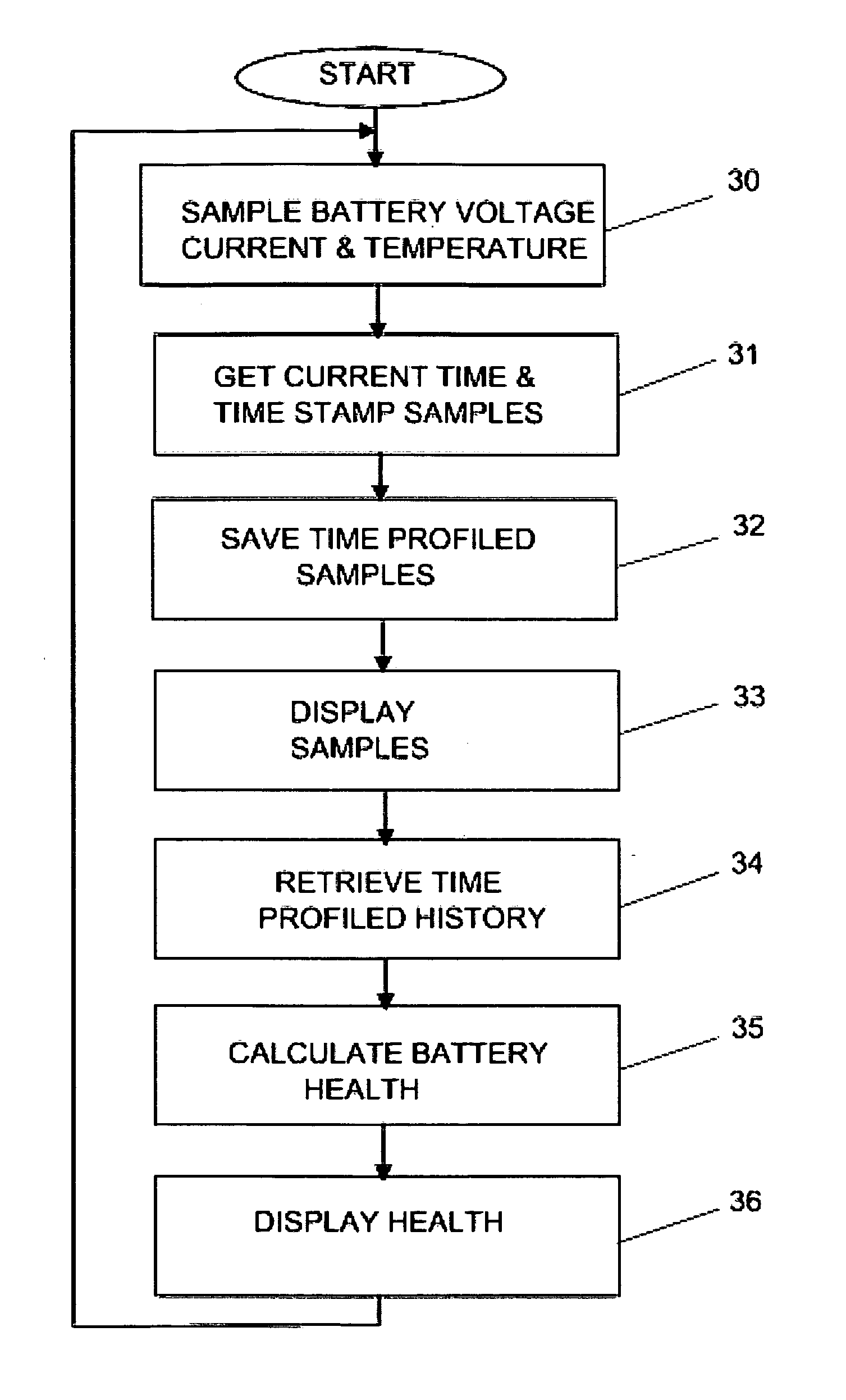
[0025]The following descriptions are provided to enable any person skilled in the art to make and use the invention and is provided in the context of six particular embodiments. Various modifications to the embodiments are possible and the generic principles defined herein may be applied to these and other embodiments without departing from the spirit and scope of the invention. Thus the invention is not intended to be limited to the embodiments shown but is to be accorded the widest scope consistent with the principles, features and teachings disclosed herein.

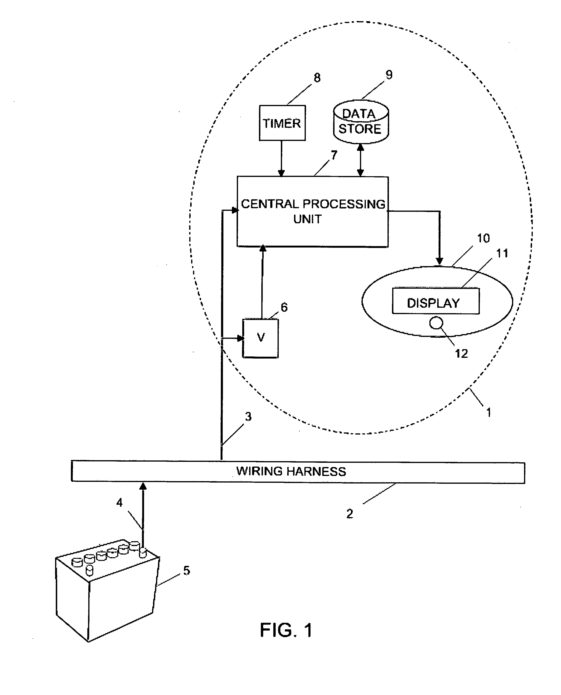
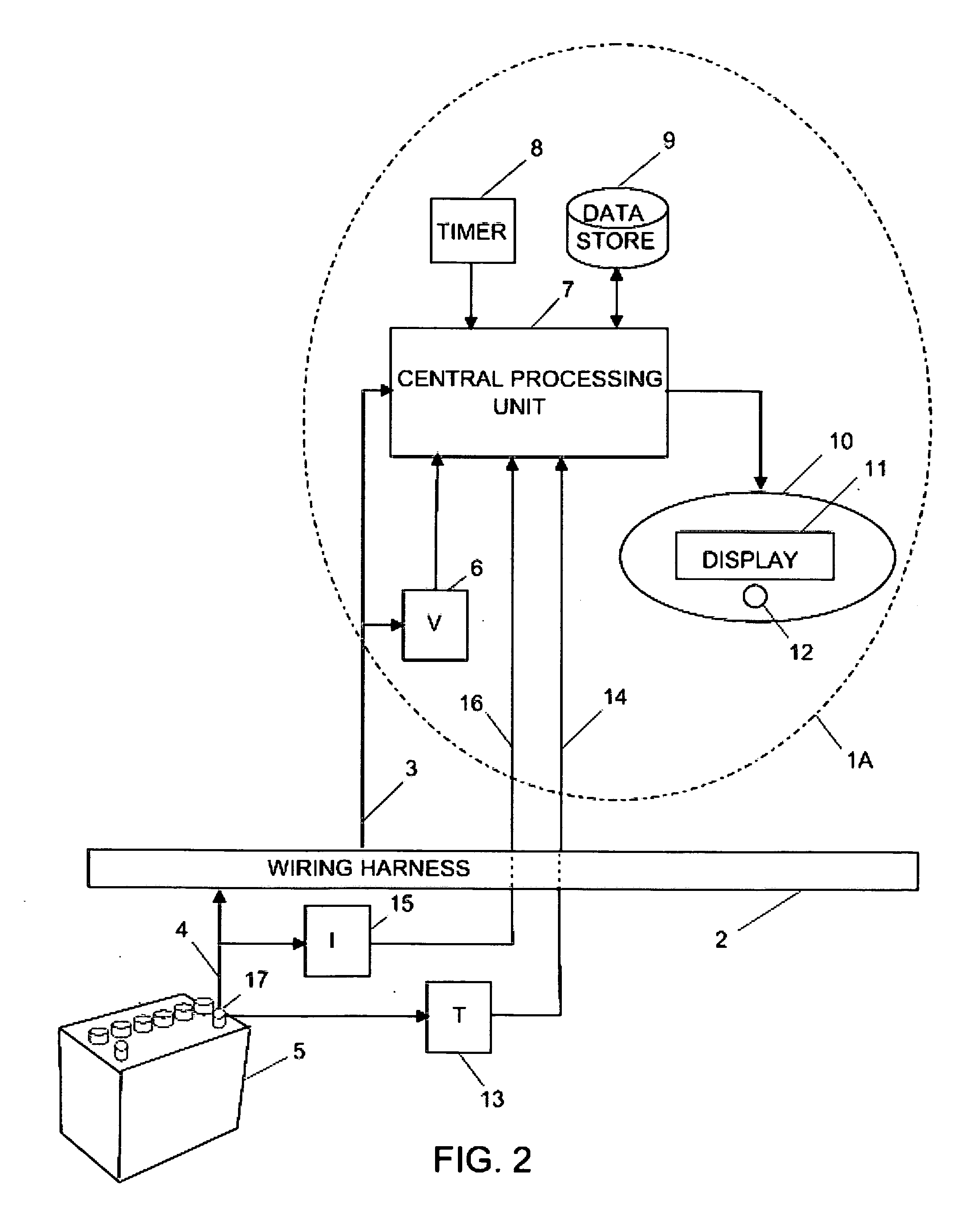
[0026]In accordance with one embodiment, the present invention provides a single-function computer system that attaches to a vehicle's wiring harness at a point that is local to the location of the vehicle's operator but remote from the location of the battery.

[0027]FIG. 1 is a block diagram illustrating a single-function environment. Computer system 1 attaches to the vehicle's wiring harness 2 using wire 3. The wiring harness...


PUM


Abstract

A computer system that installs in the proximity of the vehicle's operator, attaches to the battery power source in the vehicle's wiring harness, gathers information relating to the operational state of the vehicle's battery, calculates the health of the battery from the gathered information, provides the health and operational state of the battery to the vehicle's operator and can include the means for supporting non-battery related functions.

Description

CROSS REFERENCE TO RELATED APPLICATIONS[0001]This application is related to application Ser. No. 12 / 070,793 filed by the present inventors on Feb. 20, 2008 and entitled “Multi-function Battery Monitor System for Vehicles”.FEDERALLY SPONSORED RESEARCH OR DEVELOPMENT[0002]Not ApplicableSEQUENCE LISTING, TABLE OR COMPUTER PROGRAM LISTING ON CD[0003]Not ApplicableBACKGROUND OF THE INVENTION[0004]1. Field of Invention[0005]The present invention relates to the field of computers. In particular it relates to the gathering and analysis of information that describes the health and operational state of batteries by attaching to a vehicle's wiring harness.[0006]2. Prior Art[0007]All batteries fail. In particular the automobile battery is particularly onerous. Automobile manufactures currently provide only the real-time state of the car's charging system (alternator) when the engine is running. The battery is only one component of this system. This system warns the motorist when there is a prob...

Claims


Application Information

Patent Timeline
Patent Type & Authority Applications(United States)
IPC IPC(8): G01M17/00G06F19/00
CPCG01R31/007G01R31/3689G01R31/3679G01R31/371G01R31/392
Inventor GOFF, LONNIE CALVINCONLEY, MICHAELEIDSON, MARK
Owner BATTERYMOLE LLC
Why Eureka
Try Eureka