Imaging device

a technology of a retracting device and a spherical tube, which is applied in the direction of mountings, instruments, printing, etc., can solve problems such as interfering between, and achieve the effect of reliable retracting operation

Inactive Publication Date: 2009-09-17
HOYA CORP
View PDF10 Cites 28 Cited by
  • Summary
  • Abstract
  • Description
  • Claims
  • Application Information

AI Technical Summary

Benefits of technology

[0007]The present invention provides an imaging device which includes an axial-direction moving element and an in-plane moving optical element, wherein a balance between further miniaturization of the imaging device in the retracted state thereof and a reliable retracting operation of the imaging device is achieved in which the axial-direction moving element and the in-plane moving optical element do not interfere with each other.

Problems solved by technology

If a retractable lens is combined with such a type of shake reduction system, so as to constitute a camera system, and miniaturization of this camera system is pursued, a problem of interference arises between the axial-direction moving member of the retractable lens and the in-plane moving optical element of the shake reduction system in a fully-retracted state of the lens barrel.

Method used


Image

  • Imaging device
  • Imaging device
  • Imaging device

Examples


Embodiment Construction

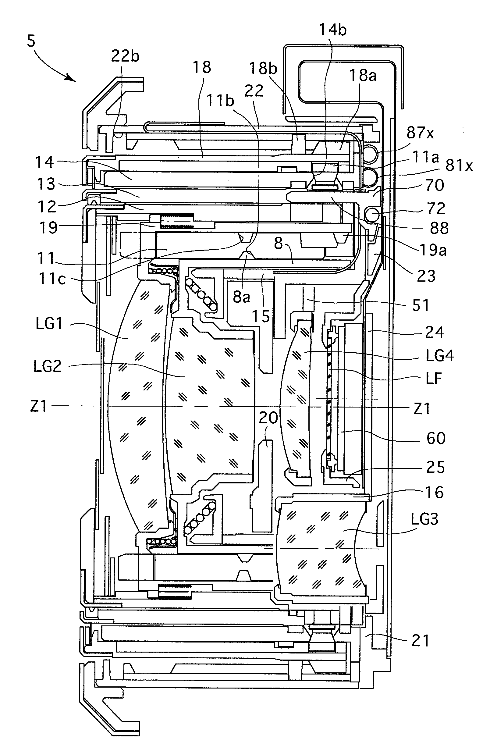
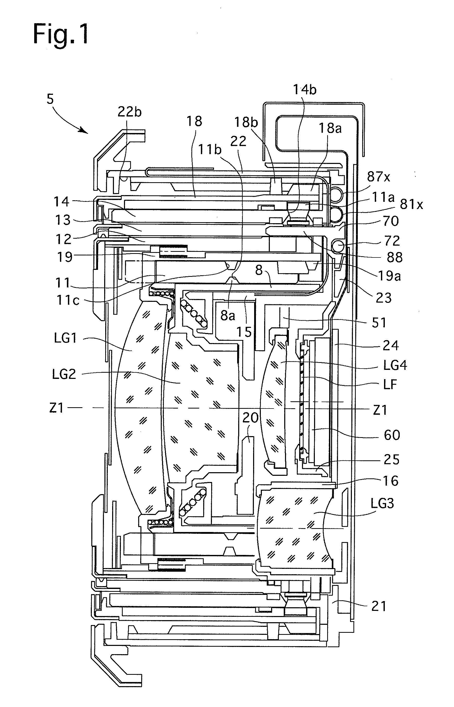
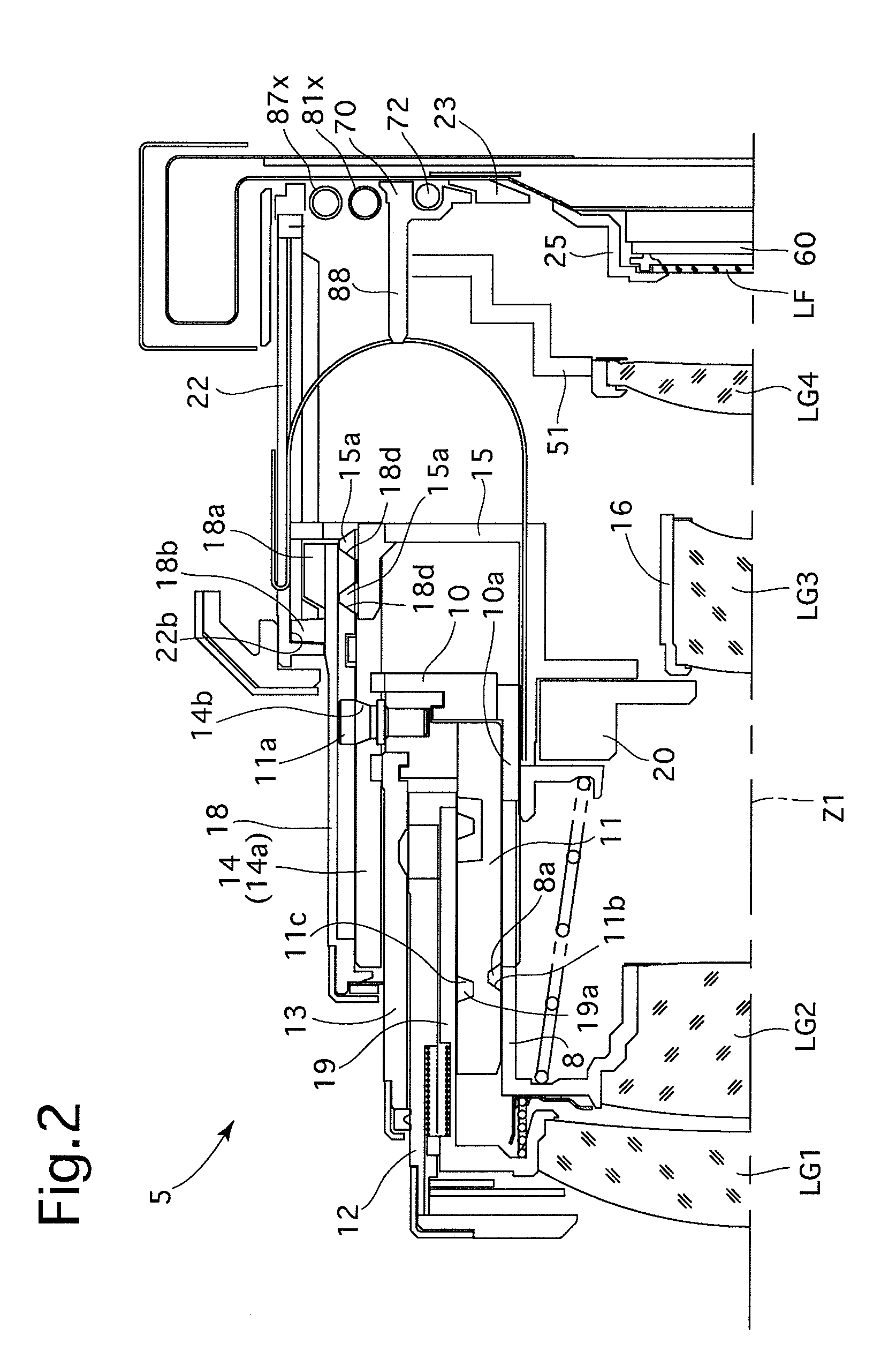
[0060]An embodiment of a zoom lens (zoom lens barrel) 5 according to the present invention is incorporated in a digital camera (imaging device). The zoom lens 5 is provided with an imaging optical system which includes a first lens group LG1, a second lens group LG2, a third lens group (radially-retractable lens group) LG3, a fourth lens group LG4, a low-pass filter (optical filter) LF and a solid-state image sensor (hereinafter referred to as an image sensor) 60, in that order from the object side in a ready-to-photograph state as shown in FIG. 2 or 3. “Z1” shown in FIGS. 1 through 3, etc., designates the optical axis of the imaging optical system that is configured as a zoom optical system. A zooming operation is carried out by moving the first lens group LG1, the second lens group LG2 and the third lens group LG3 along the optical axis Z1 in a predetermined moving manner, and a focusing operation is carried out by moving the fourth lens group LG4 along the optical axis Z1. In the...


PUM


Abstract

An imaging device includes an axial-direction moving member which moves between an operating position and a retracted position in an optical axis direction, an in-plane moving optical element movable in a plane orthogonal to the optical axis, a controller which moves the in-plane moving optical element in the orthogonal plane to a reference position when the image device changes from the operating state to the retracted state, and a mechanical guide device, provided between the axial-direction moving member and the in-plane moving optical element. In a state where the in-plane moving optical element is deviated from the reference position, the mechanical guide device guides the in-plane moving optical element to the reference position by using a moving force of the axial-direction moving member when the axial-direction moving member moves from the operating position to the retracted position.

Description

BACKGROUND OF THE INVENTION[0001]1. Field of the Invention[0002]The present invention relates to an imaging device which includes an axial-direction moving member and an in-plane moving optical element. The axial-direction moving member moves along an optical axis, and the in-plane moving optical element moves in a plane orthogonal to the optical axis. The present invention relates particularly to a retracting structure of the imaging device.[0003]2. Description of the Related Art[0004]Retractable lenses (retractable lens barrels) are widely used in optical devices such as digital cameras. In addition, cameras with a shake reduction system (image stabilizer) which moves an image pickup device (image sensor) in a plane orthogonal to an optical axis of a lens system so as to reduce image shake are known in the art (e.g., Japanese Unexamined Patent Publication No. 2006-157833 and Japanese Unexamined Patent Publication 2007-128055).[0005]Retractable lenses are provided with at least one...

Claims


Application Information

Patent Timeline
Patent Type & Authority Applications(United States)
IPC IPC(8): G02B27/64G02B15/14
CPCG02B27/646G03B5/00G03B2205/0007G03B17/12G03B17/04
Inventor NOMURA, HIROSHISUZUKA, SHINYASASAKI, TAKAMITSUENDO, KENSUZUKI, TOSHIHARUISHIZUKA, KAZUNORI
Owner HOYA CORP
Why Eureka
Try Eureka