Wall panel system with insert

a wall panel and insert technology, applied in the direction of walls, parkings, ceilings, etc., can solve the problems of high construction cost of commercial and industrial buildings, long life of metal and composite wall panel systems, and inability to substitute for wood

Inactive Publication Date: 2009-10-01
FIRESTONE BUILDING PRODS
View PDF55 Cites 95 Cited by
  • Summary
  • Abstract
  • Description
  • Claims
  • Application Information

AI Technical Summary

Problems solved by technology

One such factor is the high cost to construct commercial and industrial buildings, which tend to be relatively large, from stone or brick.
Wood is not a suitable substitute due to the large loads the buildings supporting structure must withstand.
Consequently, the metal and composite wall panel systems have a long life, and may require less maintenance than other alternative building materials and systems.
Architectural wall panel systems have many advantages, as discussed above, however, these systems may also present a number of challenges and disadvantages.
One such challenge is the thermal expansion and contraction of the wall panels.
The metal and composite materials most commonly used in architectural wall panel systems are subject to natural expansion and contraction due to changes in atmospheric conditions, including heat and humidity.
If a means of accommodating this inherent thermal cycling is not provided in the attachment system of the architectural wall panel system then the panels can become warped and cracked, requiring repairing or replacement.
Another challenge that may be associated with architectural wall panel systems is directly related to the first issue of thermal cycling, and relates to the effectiveness of sealants used in joints between adjacent wall panels in face-sealed architectural panel systems.
Because the joints increase and decrease in size during thermal cycling, sealants often become dislodged and/or cracked and are thereafter ineffective at preventing the infiltration of air and water.
As a result, sealants used in face-sealed architectural panel systems have proven disappointingly ineffective.
Another disadvantage associated wit

Method used


Image

  • Wall panel system with insert
  • Wall panel system with insert
  • Wall panel system with insert

Examples


Embodiment Construction

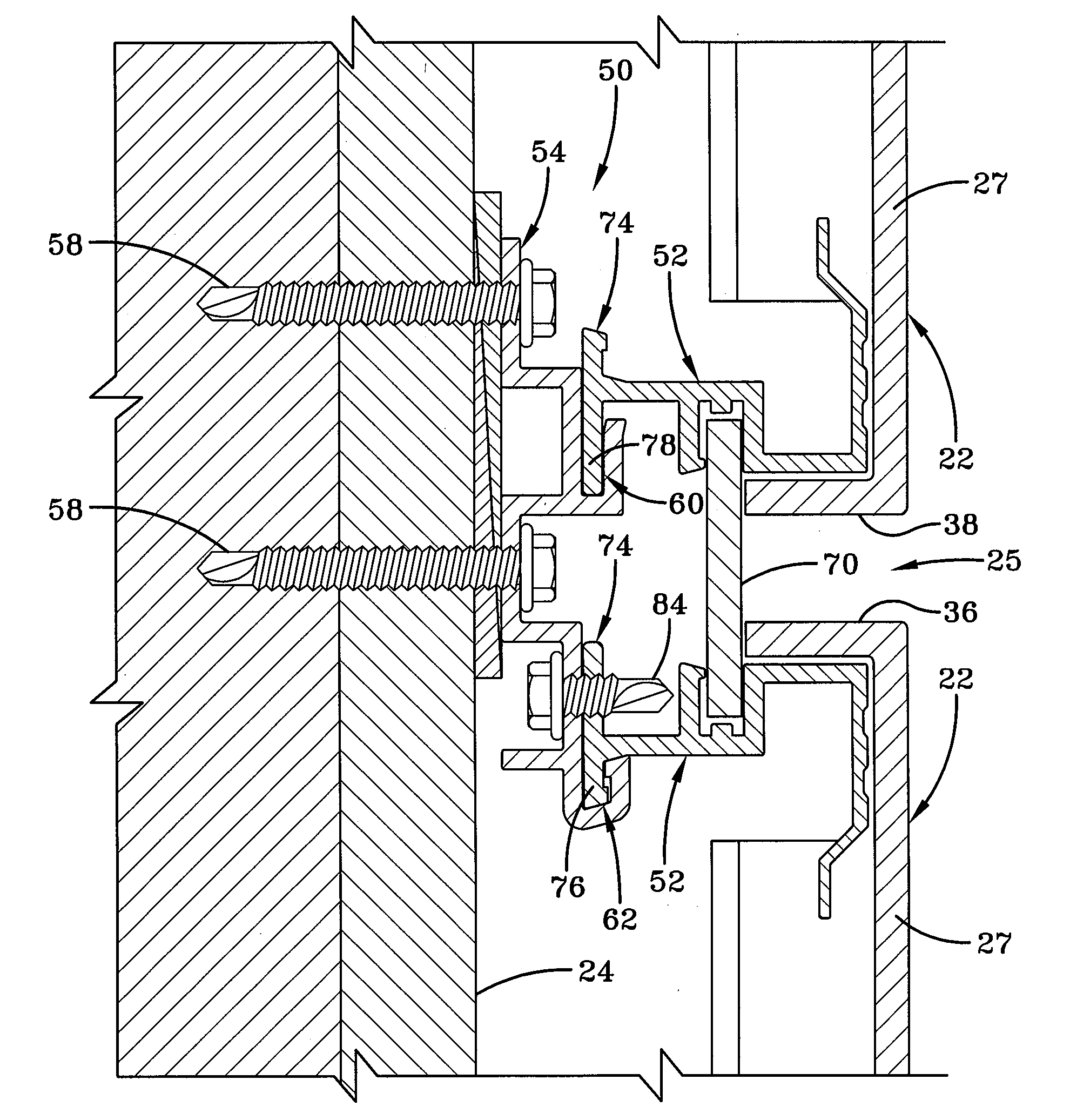
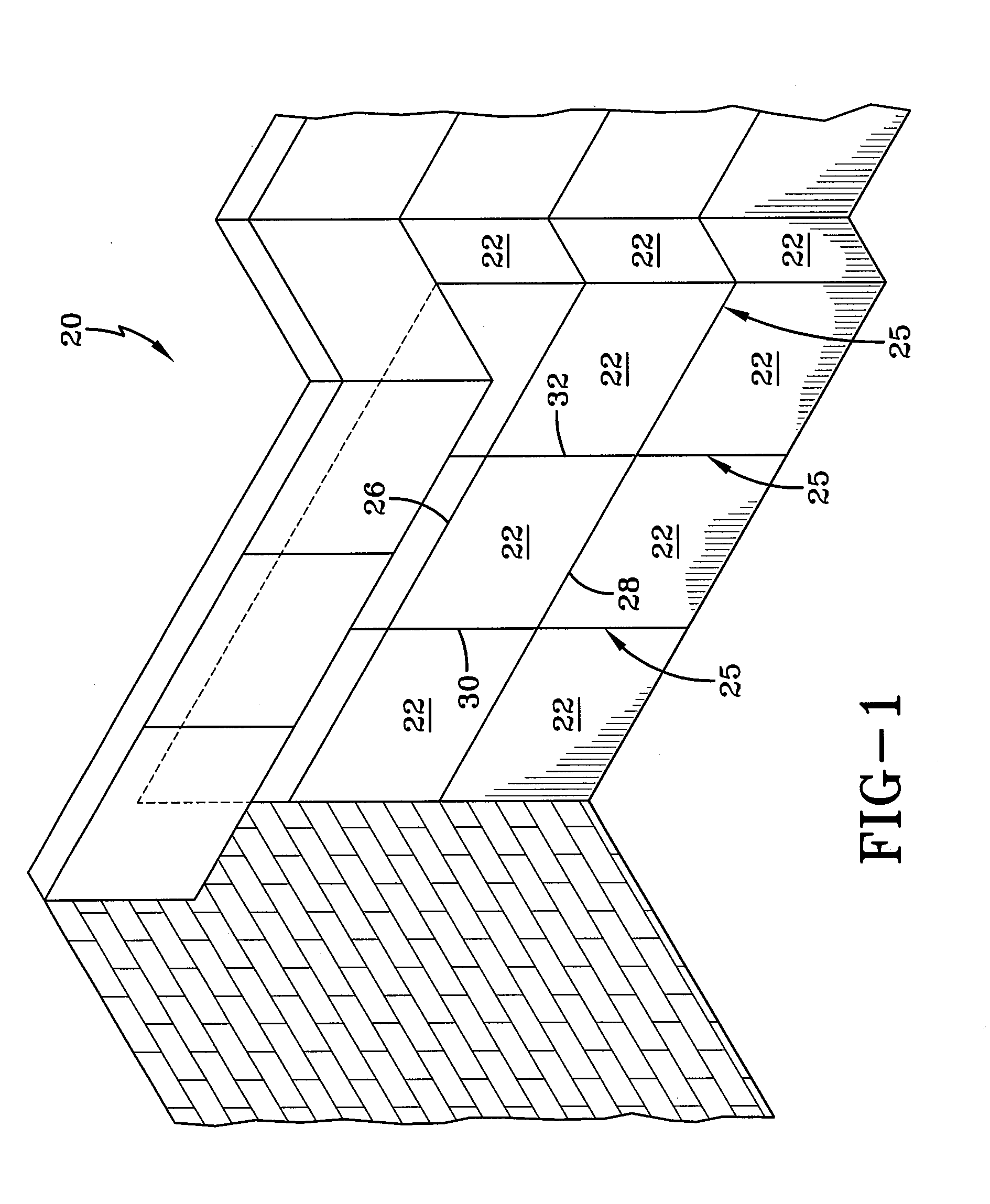
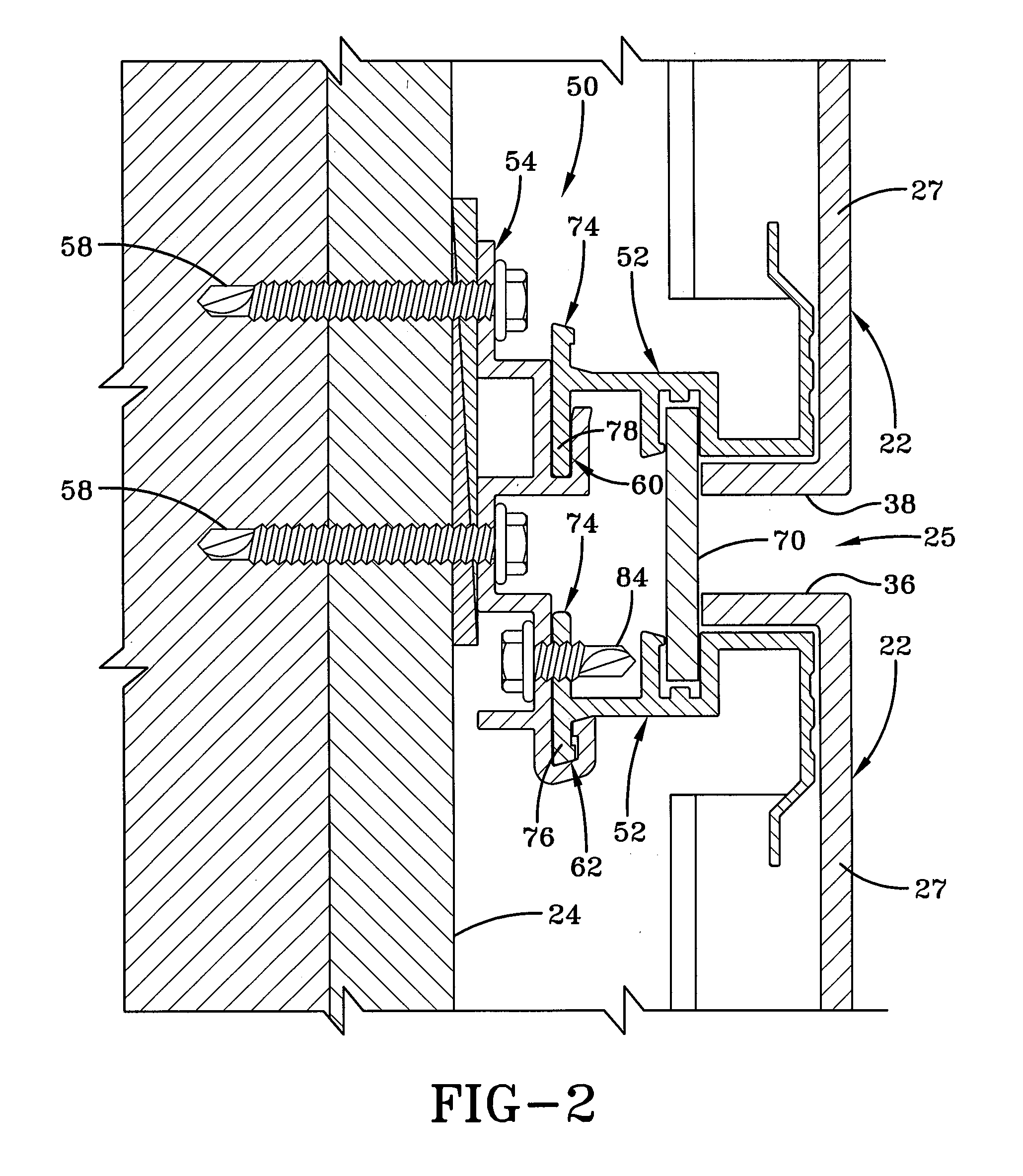
[0018]In one or more embodiments of the present invention an architectural wall panel system (hereinafter referred to as wall panel system) is provided, and is generally indicated by the numeral 20 in FIG. 1. With reference to FIG. 2, an exemplary wall panel system 20 is shown as installed on a building surface 24. Wall panel system 20 includes a plurality of wall panels 22 positioned adjacent to one another on a surface, such as building surface 24 (FIG. 2). While reference will be made herein to building surface 24, it should be appreciated that wall panel system 20 may be used on any desired surface, whether interior or exterior, and reference to building surface 24 should not be interpreted as limiting the scope of the invention.

[0019]Wall panels 22 may be made of any suitable material that has the strength and wear characteristics to withstand the natural forces and elements that act upon the wall panel system. Such materials will be readily apparent to a person of ordinary ski...


PUM


Abstract

A wall panel system including a mounting bracket, a wall panel, and a clip attached to the wall panel, the clip having an engaging element that secures it to the mounting bracket. The wall panel system also includes a slot in the clip facing outwardly from the wall panel, a spline slidably positioned in the slot of the clip, and a sealing insert positioned between the mounting bracket and the spline. The sealing insert may be in the shape of an X, and may be made from polypropylene foam. The sealing insert may also have a gasket tape on one side to provide an improved seal.

Description

[0001]This application gains the benefit of U.S. Provisional Application No. 61 / 041,449 filed Apr. 1, 2008, which is incorporated herein by reference.FIELD OF THE INVENTION[0002]One or more embodiments of this invention relate to an architectural wall panel system designed to cover an interior or exterior building surface. More particularly, one or more embodiments of this invention relate to an architectural wall panel system with a foam closure for sealing the wall panel system to prevent water and air infiltration.BACKGROUND OF THE INVENTION[0003]Architectural wall panel systems, including both metal and composite wall panel systems, have been used extensively for some time, primarily in the commercial and industrial building markets. In recent years the popularity of composite wall panel systems, in particular, has been increasing steadily. There are a number of factors that may be credited for the wide-spread and increased use of such wall panel systems. One such factor is the ...

Claims


Application Information

Patent Timeline
IPC IPC(8): E04B2/88E04C2/00E04B2/96
CPCE04F13/081E04F13/12E04F13/0889
Inventor GRIFFITHS, ROBERT T.
Owner FIRESTONE BUILDING PRODS
Why Eureka
Try Eureka