Vehicle blind spot detection and indicator system

a technology of vehicle blind spot and indicator system, which is applied in the direction of scene recognition, instruments, analogue processes for specific applications, etc., can solve the problems of driver memory difficulties, safety hazards, and use of multiple lights,

Inactive Publication Date: 2009-10-01
HONDA MOTOR CO LTD
View PDF28 Cites 48 Cited by
  • Summary
  • Abstract
  • Description
  • Claims
  • Application Information

AI Technical Summary

Problems solved by technology

The use of multiple lights, particularly those differing in color, or those emitting sounds, can distract a driver and thus become a safety hazard.
As previously noted, the use of multiple lights can distract a driver.
And depending upon how the multiple lights are configured, a driver may experience difficulty in remembering what each display pattern or mode of operation of the lights represents.
In addition, providing multiple lights increases costs and is undesirable as a result of greater complexity and costs during maintenance or repair of the system.
However, with the increasing amounts of electronics and associated controls and displays provided in vehicles, available area on the dash or instrument panel has decreased.
Although beneficial in many regards, placement of such indicators in external mirrors is not always desirable particularly in environments where snow and ice can collect on such mirrors.

Method used


Image

  • Vehicle blind spot detection and indicator system
  • Vehicle blind spot detection and indicator system
  • Vehicle blind spot detection and indicator system

Examples


Embodiment Construction

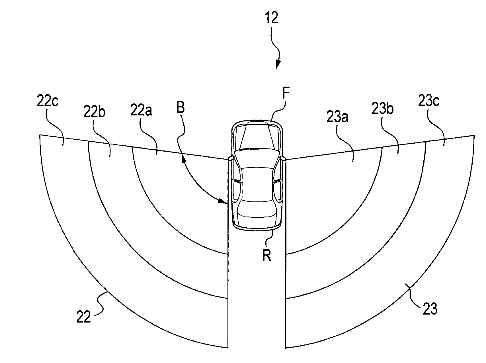
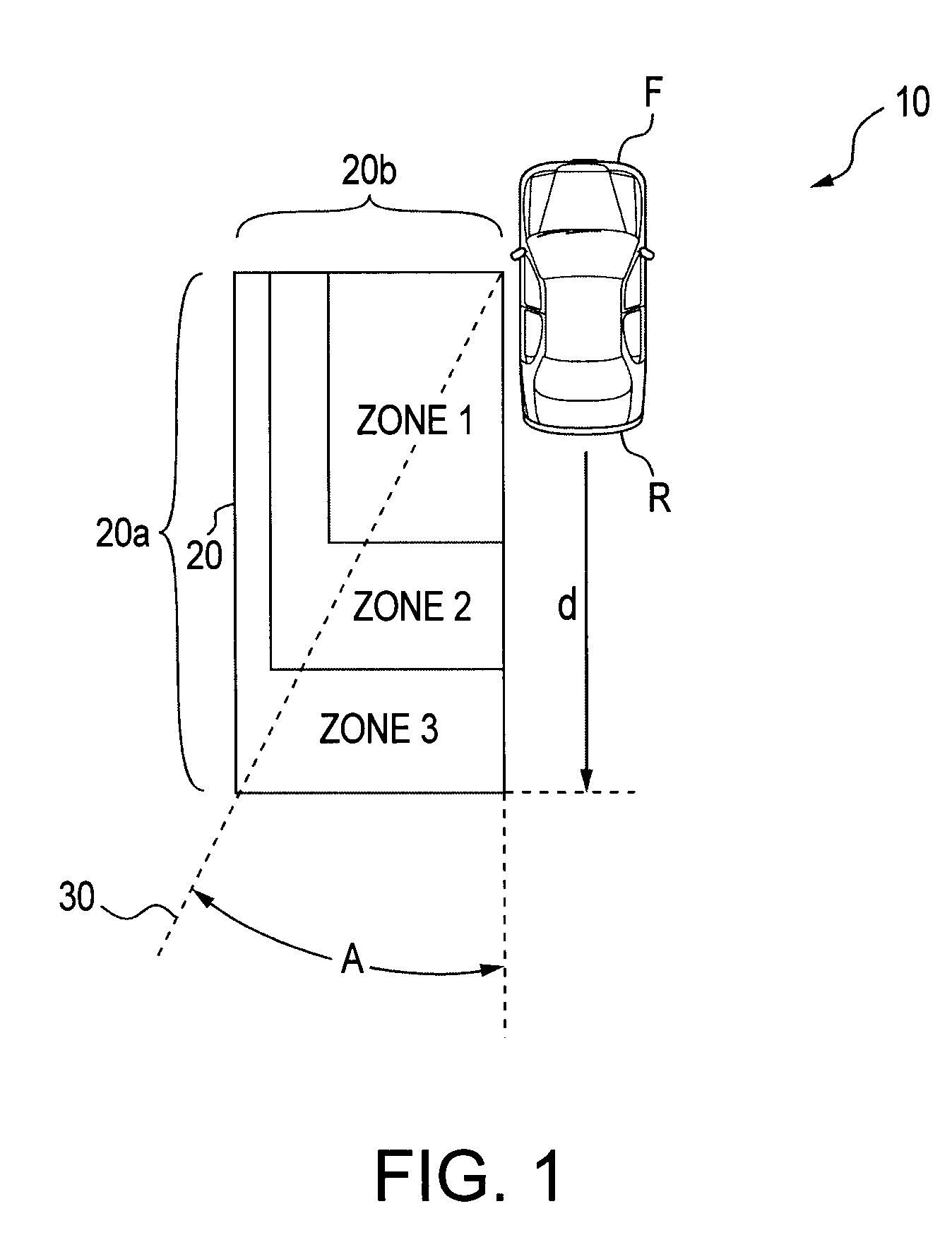
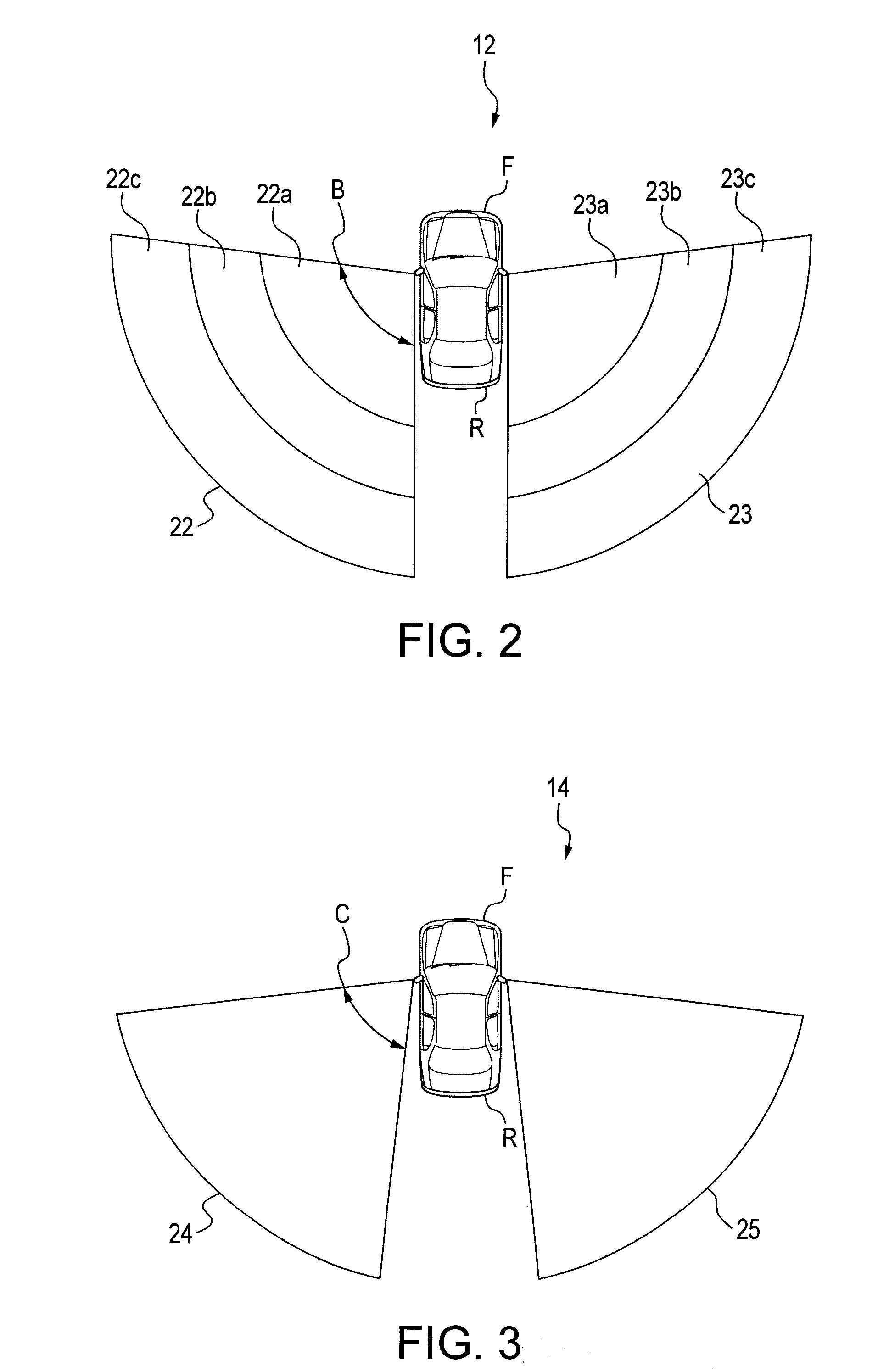
[0034]The present invention relates to vehicle blind spot detection and indicator systems. Specifically, the present invention is directed to light emitting indication systems for conveying information to a driver regarding the state of the blind zone and proximity of vehicle(s) therein. The invention is also directed to methods for detecting the presence and proximity of vehicle(s) in a blind zone and providing a visual indication of such presence and proximity to a driver. In addition, the invention is directed to methods for indicating advisability of a lane change to a driver. And, the present invention is directed to methods of indicating the degree of danger associated with a contemplated lane change.

[0035]The terms “blind spot” or “blind zone” as used herein refer to areas external to a vehicle that can not be seen by the driver of the vehicle while looking forward or through either the rear view or side mirrors. The areas typically referred to as blind spots are the rear qua...


PUM


Abstract

A warning system for conveying alerts and information relating to a vehicle blind spot and objects detected therein, is disclosed. The system conveys an assortment of information through a single light emitting indicator. Also disclosed are various methods of indicating the advisability of lane changes, and modes of configuring the indicator and an associated sensing system and controller.

Description

CROSS-REFERENCE TO RELATED APPLICATIONS[0001]This application claims priority upon U.S. provisional application Ser. No. 61 / 040,825 filed Mar. 31, 2008.BACKGROUND OF THE INVENTION[0002]The presently disclosed embodiments are directed to the field of vehicle sensing and indication systems for conveying information to a driver as to the presence and proximity of one or more objects, such as other vehicles, in the driver's blind spot.[0003]It is well known to provide driver warning systems in vehicles to warn of impending collisions. The prior art describes numerous systems that provide visual, audible, and tactile indications to a driver of a potential collision. The terms “blind spot” or “blind zone” as used in the prior art, generally refer to the rearward lateral regions along the left and right exterior sides of a vehicle. These regions are generally hidden from view of the driver when looking into the rear view and / or side mirror(s) of the vehicle.[0004]U.S. Pat. No. 5,173,881 di...

Claims


Application Information

Patent Timeline
Patent Type & Authority Applications(United States)
IPC IPC(8): B60Q1/00
CPCG06K9/00805B60Q9/008G08G1/167G06V20/58
Inventor HINNINGER, CHRISTOPHERMURATA, MAKOTOSHINGYOJI, MASAHITONAKAMURA, FUMIEFUJITA, YASUHIKO
Owner HONDA MOTOR CO LTD
Why Eureka
Try Eureka