Component mounting apparatus, mounting-component producing method, and conveyor apparatus

Inactive Publication Date: 2009-10-08
SONY CORP
View PDF12 Cites 22 Cited by
  • Summary
  • Abstract
  • Description
  • Claims
  • Application Information

AI Technical Summary

Benefits of technology

[0027]The moving of at least one of the third conveyor and the fourth conveyor includes moving, while the second component is being mounted on a first substrate as the substrate on the fourth conveyor, the third conveyor that has received a second substrate as the substrate loaded in the load area after the first substrate is loaded, so that the third conveyor is aligned with the fourth conveyor. Accordingly, it is possible to convey the second substrate from the third conveyor to the fourth conveyor immediately after the second component is mounted on the first substrate on the fourth conveyor, and mount the second component on the second substrate on the fourth conveyor. Thus, the replacement time of the first substrate and the second substrate can be shortened.
[0028]The moving of at least one of the first conveyor and the second conveyor includes moving, while the first c

Problems solved by technology

As described above, because the substrates are moved in the y direction to be conveyed to the respective mounting areas after

Method used


Image

  • Component mounting apparatus, mounting-component producing method, and conveyor apparatus
  • Component mounting apparatus, mounting-component producing method, and conveyor apparatus
  • Component mounting apparatus, mounting-component producing method, and conveyor apparatus

Examples


Example

[0054]Hereinafter, embodiments of the present invention will be described with reference to the drawings.

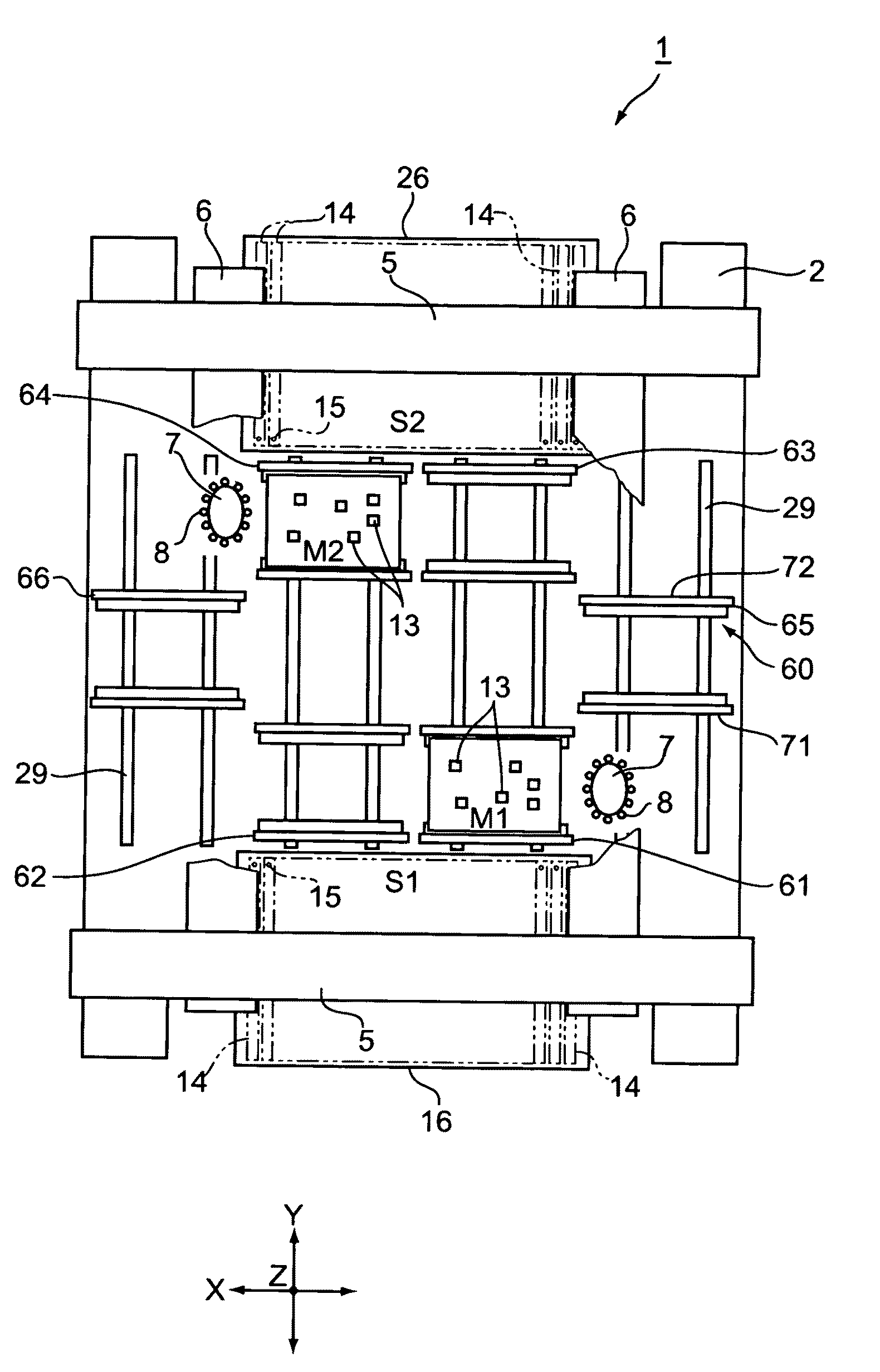
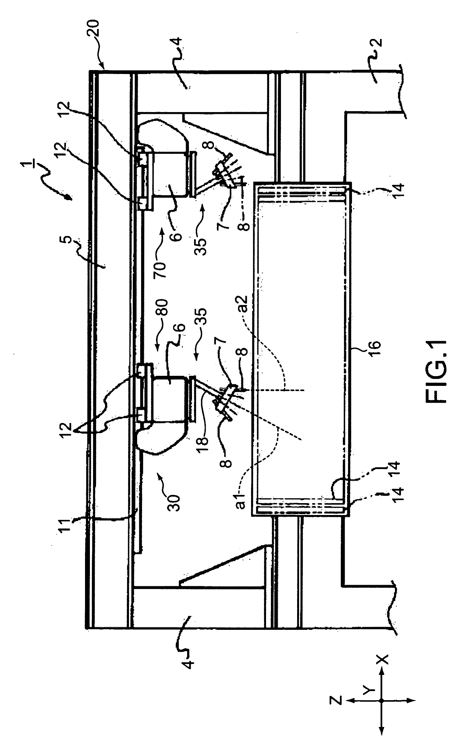
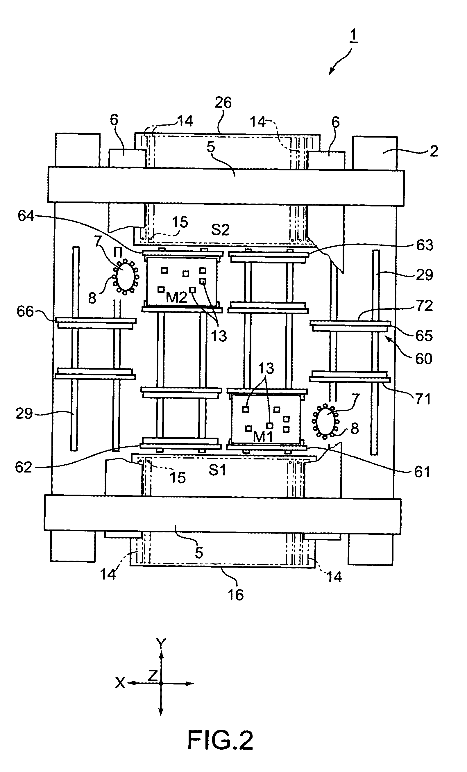
[0055]FIG. 1 is a front view of a component mounting apparatus 1 according to an embodiment of the present invention. FIG. 2 is a plan view of the partially-fractured component mounting apparatus 1. FIG. 3 is a side view of the component mounting apparatus 1. FIG. 4 is a plan view of the component mounting apparatus 1 shown in FIG. 2, for explaining each area of the component mounting apparatus 1.

[0056]As shown in FIG. 4, the component mounting apparatus 1 includes, along a direction in which a circuit board (hereinafter, simply referred to as substrate) 9 flows, that is, an X-axis direction in FIG. 4, a load area 21, a main area 22, and an unload area 23.

[0057]A load conveyor 65 that loads the substrates 9 from outside the component mounting apparatus 1 and conveys the loaded substrates 9 to the main area 22 is disposed in the load area 21. A conveyor group including first to fo...


PUM

PropertyMeasurementUnit
Areaaaaaaaaaaa

Abstract

A component mounting apparatus includes: a load area to load a substrate; an unload area to unload the substrate; a main area interposed between the load and unload areas, including a first area including a first mounting area, a second area including a second mounting area, and a third area interposed therebetween; two mounting units to mount, on the substrate, first and second components in the first and second mounting areas, respectively; a conveyor group to convey the substrate, including first to fourth conveyors, the second and fourth conveyors being capable of receiving the substrate from the first and third conveyors in the first and second areas, respectively; and a driving mechanism capable of moving at least one of the first and second conveyors between the first and third areas and moving at least one of the third and fourth conveyors between the second and third areas.

Description

BACKGROUND OF THE INVENTION [0001]1. Field of the Invention[0002]The present invention relates to a component mounting apparatus for mounting a component such as an electronic component on a circuit board or the like, a method of producing the mounting component, and a conveyor apparatus typically used in the component mounting apparatus.[0003]2. Description of the Related Art[0004]From the past, a mounting apparatus for mounting an electronic component on a substrate includes a horizontally-moving head that holds the electronic component. A nozzle for absorbing the electronic component by vacuum suction, for example, is attached to the head. By a vertical movement of the nozzle, the nozzle is brought close to the substrate to thus mount the electronic component on the substrate (see, for example, Japanese Patent Application Laid-open No. 2007-227617 (paragraph [0047], FIGS. 5 to 7); hereinafter, referred to as Patent Document 1).[0005]The mounting apparatus of Patent Document 1 inc...

Claims


Application Information

Patent Timeline
IPC IPC(8): B65G49/00
CPCH05K13/0452H05K13/0061H05K13/0015
Inventor KIMURA, AKIRAOHNO, KATSUHIKOSAITO, ATSUSHI
Owner SONY CORP
Why Eureka
Try Eureka