Permanent magnet rotating electric machine and electric power steering device using the same
a permanent magnet and electric motor technology, applied in the direction of dynamo-electric machines, electrical apparatus, magnetic circuits, etc., can solve the problems of increasing the less the height of the end portion of the permanent magnet in the peripheral direction, and the more so as to reduce the cogging torque and reduce the probability of irreversible demagnetization
- Summary
- Abstract
- Description
- Claims
- Application Information
AI Technical Summary
Benefits of technology
Problems solved by technology
Method used
Image
Examples
embodiment 1
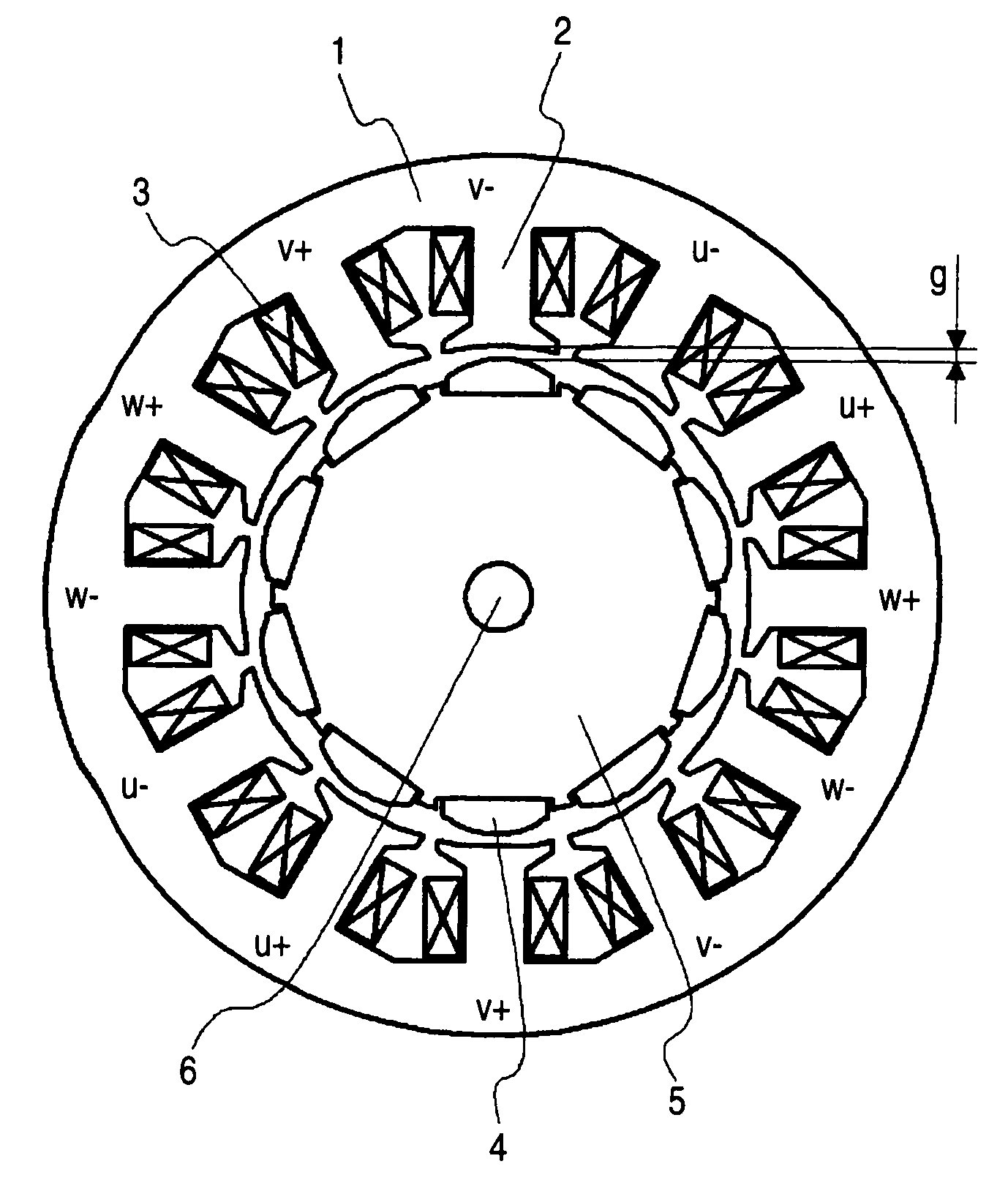
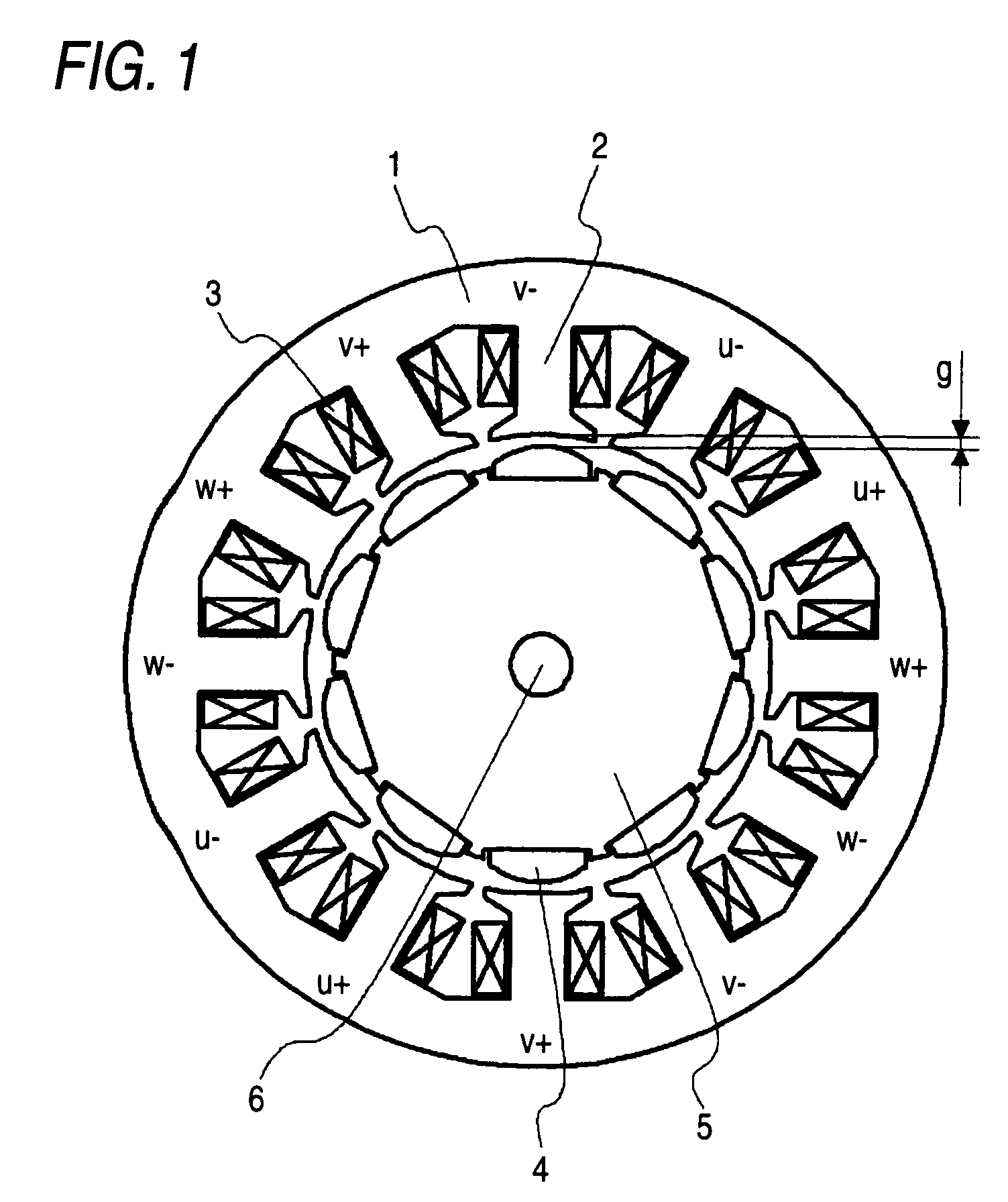
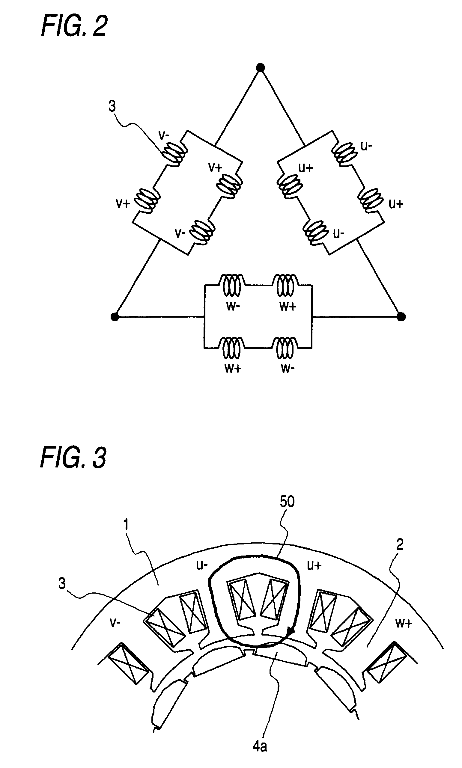
[0032]FIG. 1 is a constitutional view of a permanent magnet rotating electric machine according to an embodiment 1 of the present invention, showing the cross section of the permanent magnet rotating electric machine as seen from the axial direction. In FIG. 1, the permanent magnet rotating electric machine is shown in a simplified form by omitting the detailed parts of a frame or insulator, and a metallic tube for preventing the scattering of magnet. A stator core 1 has teeth 2 projecting inward. The teeth 2 are arranged in the peripheral direction. The permanent magnet rotating electric machine is composed of a stator and a rotor, in which the rotor is arranged to be spaced apart from the stator with an gap of an air gap length g therebetween. The gap length g is defined as the distance between the stator opposed surface of a permanent magnet 4 and the top end of the teeth 2, as shown in FIG. 1. The stator comprises a stator core 1, the teeth 2, and an armature winding 3. The arma...
embodiment 2
[0049]FIGS. 9A and 9B are partially enlarged views of a rotor for a permanent magnet rotating electric machine according to an embodiment 2 of the invention, showing a part of the rotor in cross section as seen from the axial direction. In the permanent magnet rotating electric machine of this embodiment, the shape of the projection portion provided between the adjacent permanent magnets is set more minutely than in the embodiment 1. In FIGS. 9A and 9B, the same reference numerals designate the same or like parts as in FIG. 1, which is common throughout the entire text of the specification. Also, the form of the component represented throughout the entire text of the specification is only illustrative, but not limited to the description.
[0050]FIG. 9A shows a case for comparison where the projection portion is not provided and FIG. 9B shows a case where the projection portion 7 is provided between the adjacent permanent magnets 4. This projection portion 7 is made of magnetic materia...
embodiment 3
[0053]FIGS. 11 and 12 are the constitutional views of a permanent magnet rotating electric machine according to an embodiment 3 of the invention, showing the cross section of the permanent magnet rotating electric machine as seen from the axial direction. The permanent magnet rotating electric machine of this embodiment is different in the number of poles and the number of teeth from the embodiment 1. Though the permanent magnet rotating electric machine in which the number of poles is 10 and the number of teeth is 12 has been described in the embodiment 1, the invention is also applicable to other combinations of the number of poles and the number of teeth.
[0054]FIG. 11 shows the permanent magnet rotating electric machine in which the number of poles is 14 and the number of teeth is 12. There are twelve armature windings 3, which are arranged in the order of U+, U−, W−, W+, V+, V−, U−, U+, W+, W−, V− and V+. Herein, + and − indicate that the winding direction is reverse. With this ...
PUM
 Abstract
Description
Claims
Application Information
 - R&D
- Intellectual Property
- Life Sciences
- Materials
- Tech Scout
- Unparalleled Data Quality
- Higher Quality Content
- 60% Fewer Hallucinations
Browse by: Latest US Patents, China's latest patents, Technical Efficacy Thesaurus, Application Domain, Technology Topic, Popular Technical Reports.
© 2025 PatSnap. All rights reserved.Legal|Privacy policy|Modern Slavery Act Transparency Statement|Sitemap|About US| Contact US: help@patsnap.com


