Permanent magnet rotating electric machine and electric power steering device using the same

a permanent magnet and electric motor technology, applied in the direction of dynamo-electric machines, electrical apparatus, magnetic circuits, etc., can solve the problems of increasing the less the height of the end portion of the permanent magnet in the peripheral direction, and the more so as to reduce the cogging torque and reduce the probability of irreversible demagnetization

Active Publication Date: 2013-12-03
MITSUBISHI ELECTRIC CORP
View PDF26 Cites 8 Cited by
  • Summary
  • Abstract
  • Description
  • Claims
  • Application Information

AI Technical Summary

Benefits of technology

[0006]This invention has been made to solve the above-mentioned problems, and it is an aspect of the present invention to provide a permanent magnet rotating electric machine in which the cogging torque is decreased and also the irreversible demagnetization is decreased.
[0013]Since a permanent magnet rotating electric machine according to the invention has a plurality of permanent magnets provided in order in the peripheral direction around the rotor core, with a curved surface of the permanent magnet opposed to the stator having a radius of curvature Rm, and has the geometry satisfying the relationship 0.65≦Rm×h1 / W(h1+g)≦1.37 where the thickness of a central portion of the permanent magnet in the peripheral direction is h1, the width of the permanent magnet in the peripheral direction is W, and the air gap length between the stator and the rotor is g, the cogging torque can be decreased and the irreversible demagnetization can be decreased even by passing current through the armature winding at the high temperature.
[0014]Also, since a permanent magnet rotating electric machine according to the invention has a plurality of permanent magnets provided in order in the peripheral direction around the rotor core, with a curved surface of the permanent magnet opposed to the stator, and has the geometry satisfying the relationship 0.40≦h2 / h1≦0.73 where the thickness of a central portion of the permanent magnet in the peripheral direction is h1 and the thickness of an end portion of the permanent magnet in the peripheral direction is h2, the cogging torque can be decreased and the irreversible demagnetization can be decreased even by passing current through the armature winding at the high temperature.

Problems solved by technology

In the related-art permanent magnet rotating electric machine, though the cogging torque can be decreased by making the curved surface of permanent magnet opposed to the stator like a circular arc, there is a problem that the height of the end portion of permanent magnet in the peripheral direction is smaller, whereby the irreversible demagnetization at the end portion of permanent magnet in the peripheral direction is likely to occur.
When the permanent magnet rotating electric machine operates at the high temperature, there is another problem that the irreversible demagnetization is more likely to occur because the coercive force of permanent magnet is decreased.
If the irreversible demagnetization occurs, the torque is decreased, and the cogging torque and the torque ripple are increased because the magnetic flux produced by the permanent magnet is different from at the time of design, causing the vibration or noise.
Therefore, if it is used for the electric power steering device for automobile, the good steering feeling can not be obtained.

Method used


Image

  • Permanent magnet rotating electric machine and electric power steering device using the same
  • Permanent magnet rotating electric machine and electric power steering device using the same
  • Permanent magnet rotating electric machine and electric power steering device using the same

Examples


embodiment 1

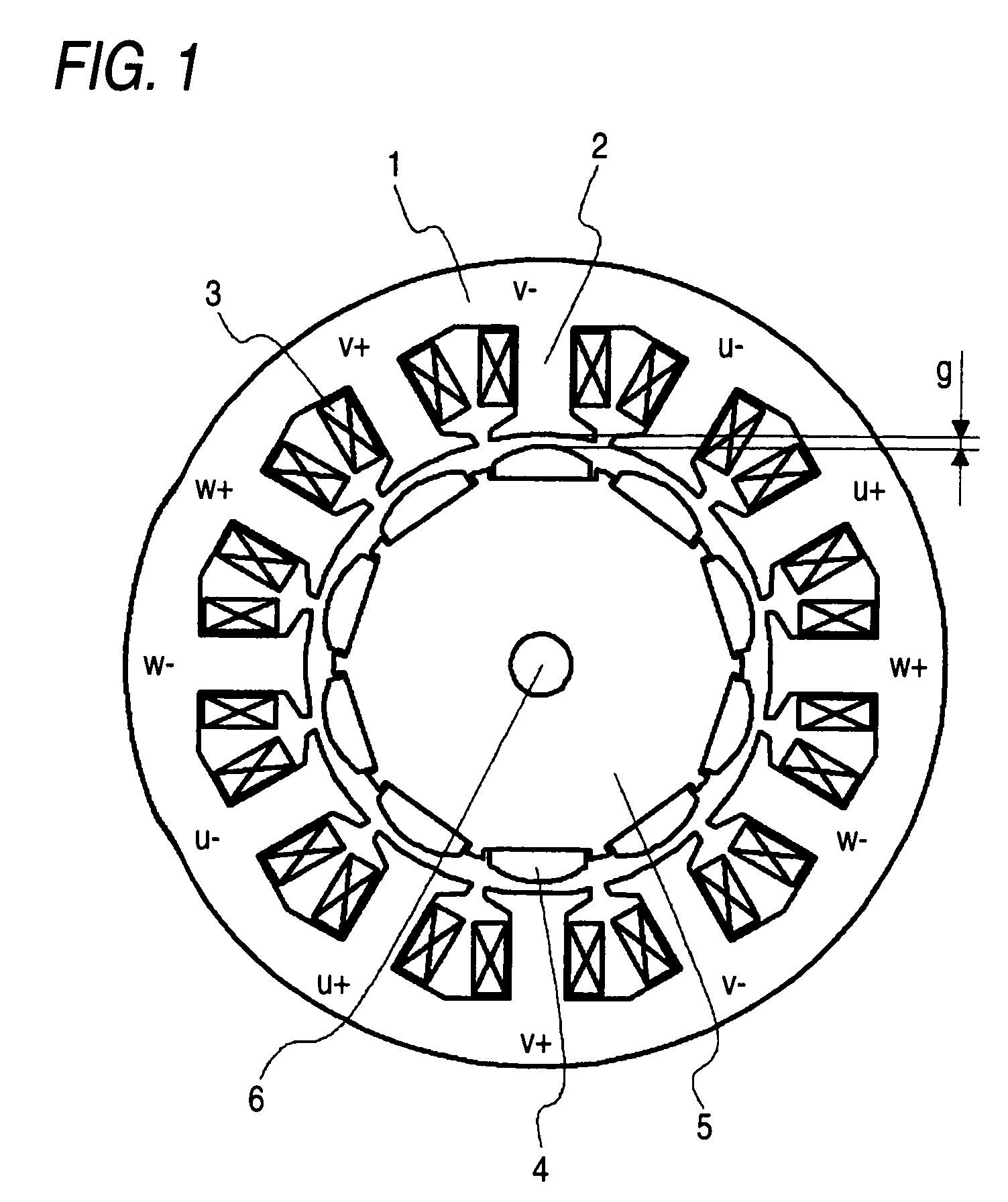
[0034]FIG. 1 is a constitutional view of a permanent magnet rotating electric machine according to an embodiment 1 of the present invention, showing the cross section of the permanent magnet rotating electric machine as seen from the axial direction. In FIG. 1, the permanent magnet rotating electric machine is shown in a simplified form by omitting the detailed parts of a frame or insulator, and a metallic tube for preventing the scattering of magnet. A stator core 1 has teeth 2 projecting inward. The teeth 2 are arranged in the peripheral direction. The permanent magnet rotating electric machine is composed of a stator and a rotor, in which the rotor is arranged to be spaced apart from the stator with an gap of an air gap length g therebetween. The gap length g is defined as the distance between the stator opposed surface of a permanent magnet 4 and the top end of the teeth 2, as shown in FIG. 1. The stator comprises a stator core 1, the teeth 2, and an armature winding 3. The arma...

embodiment 2

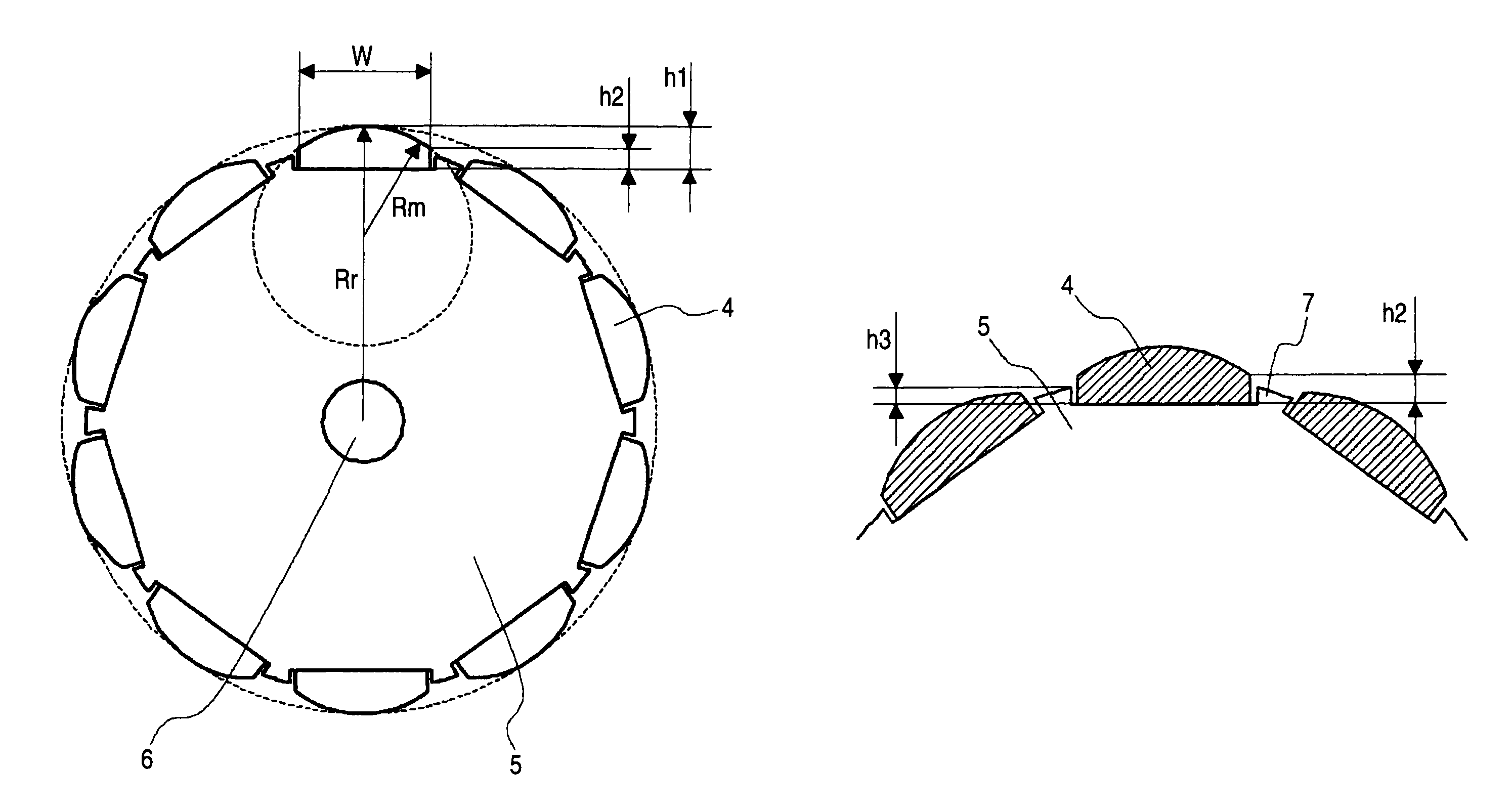
[0056]FIGS. 9A and 9B are partially enlarged views of a rotor for a permanent magnet rotating electric machine according to an embodiment 2 of the invention, showing a part of the rotor in cross section as seen from the axial direction. In the permanent magnet rotating electric machine of this embodiment, the shape of the projection portion provided between the adjacent permanent magnets is set more minutely than in the embodiment 1. In FIGS. 9A and 9B, the same reference numerals designate the same or like parts as in FIG. 1, which is common throughout the entire text of the specification. Also, the form of the component represented throughout the entire text of the specification is only illustrative, but not limited to the description.

[0057]FIG. 9A shows a case for comparison where the projection portion is not provided and FIG. 9B shows a case where the projection portion 7 is provided between the adjacent permanent magnets 4. This projection portion 7 is made of magnetic materia...

embodiment 3

[0061]FIGS. 11 and 12 are the constitutional views of a permanent magnet rotating electric machine according to an embodiment 3 of the invention, showing the cross section of the permanent magnet rotating electric machine as seen from the axial direction. The permanent magnet rotating electric machine of this embodiment is different in the number of poles and the number of teeth from the embodiment 1. Though the permanent magnet rotating electric machine in which the number of poles is 10 and the number of teeth is 12 has been described in the embodiment 1, the invention is also applicable to other combinations of the number of poles and the number of teeth.

[0062]FIG. 11 shows the permanent magnet rotating electric machine in which the number of poles is 14 and the number of teeth is 12. There are twelve armature windings 3, which are arranged in the order of U+, U−, W−, W+, V+, V−, U−, U+, W+, W−, V− and V+. Herein, + and − indicate that the winding direction is reverse. With this ...


PUM


Abstract

A permanent magnet rotating electric machine includes: a stator including: a stator core having teeth, and an armature winding wound around each of the teeth to configure the multiple phases; and a rotor including a rotor core, and permanent magnets provided in order around the rotor core. The rotor is arranged to be spaced apart from the stator with an air gap therebetween. Each of the permanent magnets has a curved surface opposed to the stator and is configured to satisfy the following relationship:0.65≤Rm×h⁢⁢1W⁡(h⁢⁢1+g)≤1.37where Rm denotes a radius of curvature of the curved surface, h1 denotes a thickness of a central portion of the permanent magnet in the peripheral direction, W denotes a width of the permanent magnet in the peripheral direction, and g denotes an air gap length of the air gap.

Description

BACKGROUND OF THE INVENTION[0001]1. Field of the Invention[0002]The present invention relates to a permanent magnet rotating electric machine, and more particularly to a motor for use in an electric power steering device for automobile, for example.[0003]2. Description of the Related Art[0004]In the related-art permanent magnet rotating electric machine, a torque pulsation called a cogging torque occurs due to an interaction between a stator core and a permanent magnet. Since the cogging torque causes vibration, it is strongly desired to decrease the cogging torque. Therefore, various techniques for decreasing the cogging torque have been proposed, and the configuration of permanent magnet to decrease the cogging torque has been examined. For example, as one example of a motor having twelve permanent magnets and nine magnetic poles, the curved surface of permanent magnet opposed to a stator is like a circular arc, the value of the radius of a rotor divided by the curvature of the su...

Claims


Application Information

Patent Timeline
Patent Type & Authority Patents(United States)
IPC IPC(8): H02K21/16
CPCH02K1/278H02K29/03H02K2213/03H02K1/2781
Inventor NAKANO, MASATSUGUTAKASHIMA, KAZUHISAAKUTSU, SATORUASAO, YOSHIHITO
Owner MITSUBISHI ELECTRIC CORP
Why Eureka
Try Eureka